Introduction
“Energy storage battery manufacturing” can describe very different facilities. One plant may manufacture cathode material, another may coat electrodes and assemble lithium-ion cells, and another may only assemble cells into modules or containerized storage systems. Their purified-water duties are not interchangeable.
This distinction is the first procurement decision. A pack-assembly site may mainly need utility or cleaning water, while a cell plant using an aqueous electrode process may need deionized water as an ingredient. Each point of use has a different risk and quality requirement.
U.S. Department of Energy research describes deionized water replacing NMP in aqueous electrode processing. It also shows why chemistry matters: many anodes use aqueous processing, while cathode routes require formulation-specific evaluation. This does not establish one universal specification for every battery plant.
This guide explains how a buyer can define the design basis, compare RO/EDI and alternative polishing routes, review storage and distribution, and write acceptance conditions that a supplier can actually test.
First Confirm What the Factory Manufactures
Before discussing resistivity, list the operations included in the project.
Battery-material production
Cathode precursor, cathode active material, anode material, conductive additives, and binder production may use water in reaction, washing, separation, cleaning, or utilities. The required water quality depends on the material chemistry and the impurities that affect that process. A material plant’s specification should therefore come from its process owner and product-quality controls.
Electrode manufacturing
Anode coating commonly uses an aqueous slurry, while conventional cathode coating may use PVDF binder with NMP solvent. Some cathode processes are also being developed or operated with aqueous routes. For any water-based formulation, the buyer should identify whether water is an ingredient, cleaning medium, or both, and which ions, organic compounds, particles, or microorganisms can interfere with slurry stability or product quality.
Cell assembly and formation
Cell assembly is sensitive to moisture, but dry-room humidity, residual electrode moisture, electrolyte handling, equipment cleaning, and water quality are distinct controls. Define the water-consuming operations instead of assuming one grade for the entire assembly area.
Module, pack, and energy-storage-system assembly
A facility assembling finished cells into modules, packs, racks, or containers may have limited direct process-water demand. Confirm the testing, cooling, cleaning, and utility users before specifying a full ultrapure-water plant.
Define Water Quality at Each Point of Use
A request such as “provide 18 megohm water” is incomplete. It states one ionic indicator but not the use, sampling location, organic load, particles, microorganisms, or allowable excursions.
ASTM D5127 provides guidance for ultrapure water in electronics and semiconductor manufacturing and emphasizes quality at the point of distribution. It is useful as a reference for how high-purity requirements can be organized, but it is not automatically a battery-manufacturing standard. The battery process owner must decide whether any of its classifications or analytical concepts are relevant.
For every user, prepare a point-of-use schedule containing:
- production step and equipment served;
- continuous, intermittent, or batch demand;
- normal and peak flow;
- required pressure and temperature;
- conductivity or resistivity at a stated reference temperature;
- limits for relevant ions such as sodium, chloride, silica, boron, calcium, magnesium, or metals;
- TOC or identified organic limits where product risk justifies them;
- particle, turbidity, or microbial limits where relevant;
- sampling location, method, frequency, and alarm response;
- maximum acceptable duration and handling of off-spec water.
Conductivity and resistivity help detect ionic contamination. ASTM D1125 covers their measurement in industrial and treated waters; lower-level high-purity measurements may require another method. State the agreed method instead of comparing instruments with different compensation or cell conditions.
Build the Design Basis from Feed Water and Demand
The same product-water target can require different equipment in two locations because feed water varies. Obtain a representative analysis and the expected seasonal range. At minimum, review:
- conductivity or total dissolved solids;
- hardness and alkalinity;
- pH and temperature;
- silica, iron, manganese, and other scaling or fouling constituents;
- free chlorine or other oxidants;
- turbidity, suspended solids, and an appropriate fouling indicator;
- TOC or identified organics when relevant;
- microbiological condition where storage or biological growth is a concern.
Demand data must go beyond a daily total. Give average and peak hourly flow, batch volume, shifts, simultaneous users, expansion, and acceptable interruption. Continuous demand is not equivalent to short high-flow batches with the same daily total.
The design should show a water balance for product water, pretreatment backwash, RO reject, EDI concentrate, flushing, cleaning, and any recovery stream. A quoted recovery percentage is meaningful only when its calculation boundary and reject-water destination are visible.
How to Select the Treatment Route
There is no mandatory train for every battery plant. The following stages are common engineering roles that must be justified against the feed analysis and point-of-use specification.
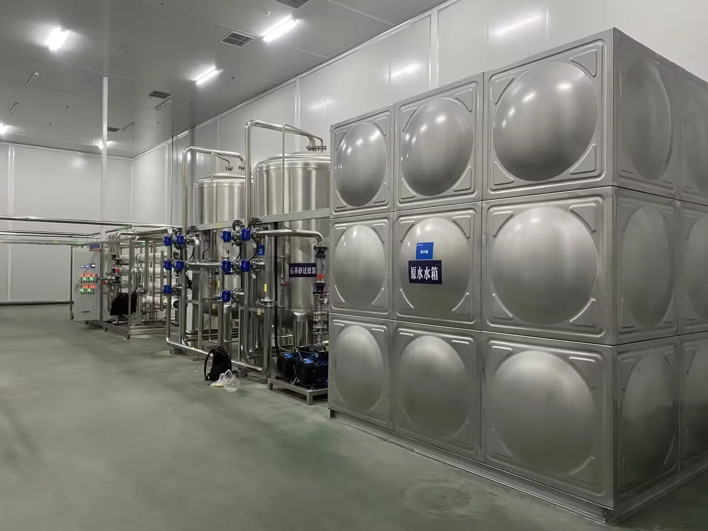
1. Feed-water conditioning
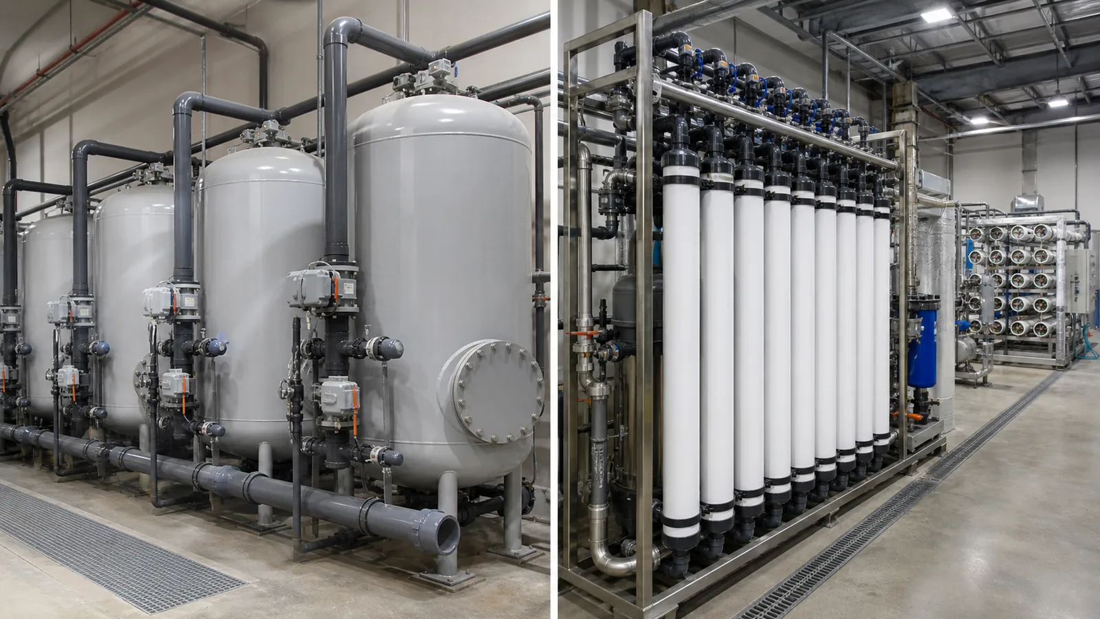
Depending on the water source, conditioning may include screening, multimedia filtration or ultrafiltration, activated carbon or another dechlorination method, softening, antiscalant dosing, cartridge filtration, pH adjustment, or combinations of these. The objective is to protect downstream membranes and stabilize operation—not to add every available unit.
The choice between multimedia filtration and ultrafiltration should consider raw-water variability, suspended material, microbiological risk, footprint, backwash demand, automation, and the required membrane feed condition. Chlorine control must match the selected RO membrane and the biological strategy for tanks and piping.
2. Reverse osmosis
RO normally provides the main dissolved-solids reduction. One-pass or two-pass design depends on feed water, product target, carbon dioxide, silica, boron, temperature, recovery, and the polishing stage. The buyer should not select two-pass RO simply because it sounds more advanced, nor accept one-pass RO without checking the full quality envelope.
A proposal should show flux, recovery, stage arrangement, membrane performance basis, pressures, normalized permeate quality, cleaning assumptions, and limiting operating temperatures. Pretreatment and dosing belong in the same guarantee discussion.
3. EDI or alternative polishing
Electrodeionization is commonly used to polish RO permeate continuously without conventional acid-and-caustic regeneration of mixed-bed resin. It removes ionized and ionizable species using membranes, ion-exchange media, and DC power. Mixed-bed ion exchange or another polishing method may still be suitable when the operating pattern, required quality, redundancy strategy, or local service model favors it.
EDI is not a substitute for proper RO pretreatment. DuPont’s EDI technical guidance highlights total exchangeable anions, carbon dioxide, hardness, and dissolved silica as important feed considerations and notes that conductivity alone does not show the complete ionic load. The buyer should therefore request the EDI feed calculation, not only a claimed product resistivity.
4. Final polishing and microbial control
Depending on the user, the system may include UV, final filtration, heat or chemical sanitization provisions, or other controls. These are not universal battery requirements. They should address an identified organic, particle, or microbial risk and be compatible with the distribution materials and production process.
Storage and Distribution Are Part of the Water System
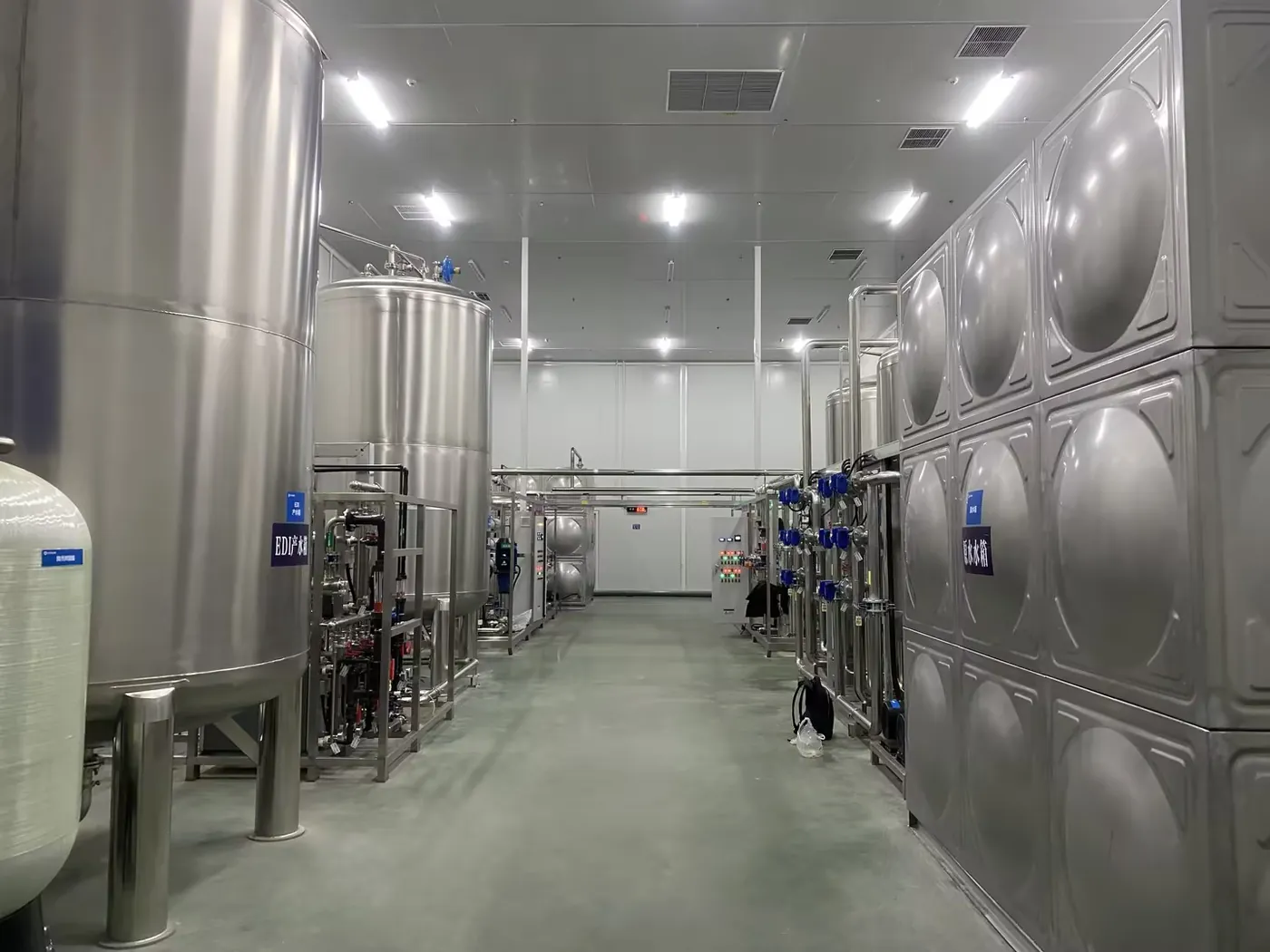
High-quality water can deteriorate after the skid. Tanks, vents, pumps, piping, branches, sampling points, idle sections, and return conditions all affect delivered quality.
The RFQ should define whether the supplier covers only generation equipment or also the product-water tank and distribution loop. Review:
- tank material, finish, vent protection, level control, overflow, drainability, and cleaning access;
- duty and standby pump philosophy;
- loop flow, pressure, return, and balancing at simultaneous demand;
- piping and seal materials compatible with the required water quality and sanitization method;
- avoidance or management of stagnant branches;
- sampling and online monitoring locations;
- off-spec diversion and the route used during start-up or sanitization;
- future connection points and expansion allowances.
Point-of-use quality should be evaluated at representative users and the loop return, not only at the EDI outlet. If the distribution system is supplied or installed by others, the performance boundary and responsibilities must be written explicitly.
Instrumentation and Quality Monitoring
Monitoring should follow the process risk and acceptance specification. Typical instruments may include feed and product flow, pressure, differential pressure, conductivity, resistivity, temperature, pH, oxidation-reduction potential, tank level, and selected online organic or silica measurements. Not every project needs every instrument.
For each critical measurement, define range, accuracy, temperature compensation, calibration, alarm limits, and response. A resistivity reading can be misleading when a sample line is stagnant, exposed to air, or poorly compensated.
The control narrative should explain start-up flushing, low-quality diversion, RO sequencing, EDI interlocks, tank-level logic, alarms, sanitization, and recovery after a trip. Procurement should include the agreed tag list, I/O list, alarm matrix, and communication interface.
Capacity, Redundancy, and Operating Cost
Size the system from a time-based demand profile, not one average flow plus a safety factor. Storage can buffer batches but also increases residence time. Apply redundancy where the production cost of interruption and maintenance plan justify it.
Ask suppliers to state the basis for:
- net product-water capacity at the guaranteed condition;
- system recovery and each reject stream;
- electrical load and major operating consumables;
- membrane cleaning frequency assumptions;
- filter and cartridge replacement assumptions;
- chemical consumption where chemicals are used;
- planned maintenance and replacement access;
- operator tasks and laboratory support.
Compare operating cost across pretreatment, pumping, cleaning, reject management, consumables, downtime, and distribution—not an isolated energy number.
Factory Testing, Shipment Inspection, and Installation Preparation
Factory acceptance testing should verify what can reasonably be proven before the equipment reaches the site. It may include:
- equipment identity, dimensions, and configuration;
- key material and component documentation;
- panel, wiring, instrument, alarm, and interlock checks;
- pump rotation, valve actuation, and sequence simulation;
- clean-water circulation and pressure checks where appropriate;
- RO or EDI module documentation and preservation condition;
- drawings, manuals, spare parts, and packing-list review.
Factory testing with available water does not automatically prove the final point-of-use quality at the customer’s site. Feed composition, temperature, final distribution piping, commissioning condition, sampling method, and operating load can all change the result.
Shipment inspection should check capped connections, protected instruments, membrane preservation, lifting points, package identification, and documents. Reconfirm voltage, frequency, control interface, documentation language, destination, and required labels before packing.
Installation preparation should confirm foundations, lifting, service clearance, pipe interfaces, drainage, power, air, feed water, reject routes, sampling, and commissioning support. A compact skid does not remove these responsibilities.
How to Define Site Acceptance
Separate acceptance into four stages:
- Mechanical completion: installation, piping, wiring, lubrication, calibration, labeling, and safety checks.
- Wet commissioning: flow, pressure, level, alarms, flushing, interlocks, and automatic sequences with an agreed safe water source.
- Quality stabilization: operation until the treatment and distribution system reaches defined stable conditions.
- Performance test: measured capacity and water quality within an agreed feed-water and operating envelope.
The protocol should state feed-water limits, temperature, net flow, operating hours, recovery definition, sampling points, instrument method, laboratory method, stabilization period, number of samples, acceptance limits, and responsibility for utilities and operators.
Accept performance at the agreed boundary. If the supplier covers the return loop, test representative users and the return. If the contract ends at the skid outlet, do not describe outlet quality as guaranteed point-of-use quality.
How to Compare Suppliers
Use the same questions for every bidder:
- Which production users and quality limits form the design basis?
- Which customer data are confirmed and which values are assumptions?
- Why is each pretreatment stage required for the stated feed water?
- Why is one-pass or two-pass RO proposed?
- What is the calculated EDI feed load, including carbon dioxide and silica where relevant?
- Where are product quality and capacity guaranteed?
- What tanks, pumps, loop piping, instruments, and sanitization provisions are included?
- How are RO reject, EDI concentrate, flushing, and cleaning water managed?
- What can be demonstrated during factory testing and what requires site testing?
- What civil works, utilities, installation work, commissioning support, consumables, and spare parts are excluded?
A lower equipment price may represent a different performance boundary, recovery, redundancy level, material selection, monitoring scope, or customer-supplied distribution system. Compare the complete water-delivery responsibility before comparing price.
FAQ
Does every energy storage battery factory need ultrapure water?
No. The requirement depends on whether the facility manufactures materials or cells, uses water in an electrode formulation, performs specified rinsing or cleaning, or only assembles finished cells into packs and systems. Define the actual water users before selecting the treatment grade.
What resistivity is required for battery manufacturing water?
There is no universal value for all battery processes. The process owner should define ionic and non-ionic limits at each point of use, along with the measurement method and allowable excursions. A resistivity value copied from semiconductor or laboratory water does not by itself form a complete battery specification.
Is RO alone sufficient?
Sometimes, but not always. RO may satisfy a defined purified-water duty when feed water and product limits allow it. Higher ionic quality or stability may require a second RO pass, EDI, mixed-bed ion exchange, or another polishing step. The decision should follow a feed-water and point-of-use calculation.
Why is EDI usually installed after RO?
EDI is designed to polish low-ionic-load RO permeate. Hardness, carbon dioxide, silica, oxidants, particles, and other feed conditions must remain within the module’s operating limits. Sending unsuitable raw or poorly treated water to EDI can reduce performance or damage components.
Can the factory acceptance test prove final ultrapure-water quality?
It can verify equipment, controls, circulation, and agreed water-quality checks under factory conditions. Final point-of-use performance normally requires the actual site feed water, installed storage and distribution system, calibrated instruments, and a written site test protocol.
What information is needed for an ultrapure-water-system quotation?
Provide the production process, point-of-use quality schedule, feed-water analysis and variability, average and peak flow, batch pattern, operating hours, required pressure, distribution scope, redundancy, utilities, footprint, automation interface, reject-water constraints, documentation, destination, and acceptance requirements.
Conclusion
The right ultrapure-water system for an energy storage battery plant is not defined by an industry label or a single resistivity number. It is defined by the production use, feed water, demand profile, point-of-use quality, distribution system, monitoring method, reject route, and acceptance boundary.
For procurement, the most reliable sequence is to map every user, confirm the relevant contaminants, select each treatment stage for a stated reason, include storage and distribution in the quality discussion, and distinguish factory equipment checks from site performance. This produces a specification that suppliers can price consistently and operators can use after commissioning.
Related Buyer Resources
- Ultrapure Water System Specification Guide
- RO vs EDI vs Mixed Bed for High-Purity Water
- Ultrafiltration vs Multimedia Filter for RO Pretreatment
- Ultrapure Water Systems
- Semiconductor, Electronics & PCB Water Treatment Solutions
References
- U.S. Department of Energy — U.S. DRIVE Highlights of Technical Accomplishments 2013
- ASTM International — D5127 Standard Guide for Ultra-Pure Water Used in the Electronics and Semiconductor Industries
- ASTM International — D1125 Standard Test Methods for Electrical Conductivity and Resistivity of Water
- DuPont Water Solutions — EDI-310 Module Manual
- DuPont Water Solutions — FilmTec System Design Technical Manual Excerpt