Introduction
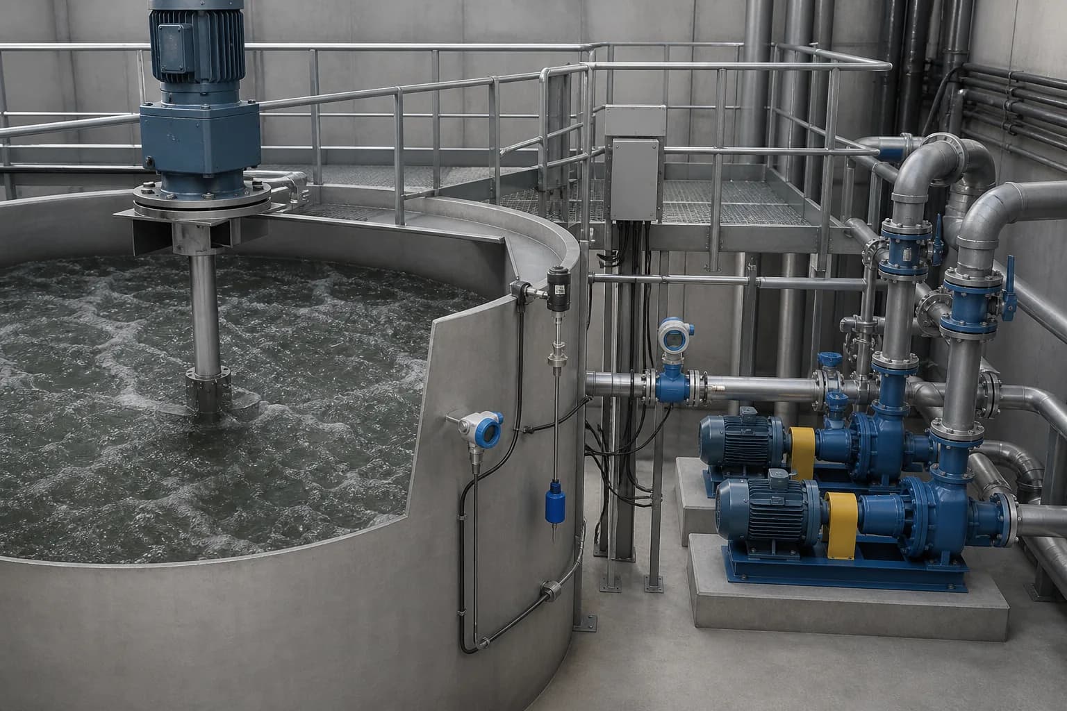
An equalization tank is often described as a simple buffer. In an industrial wastewater plant, it is more accurately a process-control asset. It receives variable water from production and releases a more stable flow and load to chemical, biological, membrane or thermal treatment. If the tank is too small, downstream equipment still sees the peaks it was meant to absorb. If it is oversized without adequate mixing, the plant can create settling, odor, stratification and unnecessary capital cost.
The practical design question is therefore not “How many hours of retention should we use?” It is “What working volume is required to absorb the actual mismatch between incoming wastewater and the rate the downstream system can safely accept?” That question requires a flow profile, operating schedule and representative water-quality data.
This guide explains a buyer-oriented sizing method, the conditions that change the result, and the information that should appear in an RFQ. It does not present a universal retention time because production patterns, wastewater chemistry and treatment objectives differ by project.
What Equalization Must Accomplish
Industrial equalization can serve several related duties:
- Hydraulic equalization. It dampens hourly inflow peaks and supplies a steadier flow to the next process.
- Load equalization. It blends high- and low-strength batches so that COD, suspended solids, salinity, metals or other constituents do not shock the downstream stage.
- pH stabilization. It can reduce short pH excursions through controlled blending, although it should not replace a properly designed neutralization system.
- Production decoupling. It allows wastewater treatment to continue at a controlled rate when production is intermittent or concentrated into one or two shifts.
- Operational reserve. It may provide limited time to respond to a process upset, cleaning discharge or maintenance event when that duty is explicitly defined.
One tank does not automatically perform every duty. A buffer intended only for hourly flow smoothing may be inadequate for a concentrated cleaning batch. An emergency holding volume may need isolation and should not be counted as normal equalization working volume. Define each duty before adding the volumes together.
Step 1: Build a Representative Inflow Profile
Average daily flow hides the peaks that determine equalization volume. Record or estimate inflow in intervals that match the process behavior. Fifteen-minute or hourly data are useful for rapid batch discharges; longer intervals may be acceptable for stable continuous production.
The profile should cover normal production, start-up, shutdown, cleaning, product changeover and the highest credible production day. Separate unusual events rather than blending them into an average. If a food plant performs a large clean-in-place discharge after each shift, or a metal-finishing line empties a rinse tank at a fixed time, those events must appear in the profile.
For every interval, document:
- inflow volume or rate;
- production activity that generated the water;
- pH, temperature and the pollutants that can govern treatment;
- whether the discharge can be rescheduled or released gradually;
- whether any stream should remain segregated for recovery, pretreatment or controlled dosing.
Where meters are not yet installed, production logs, tank dump volumes, pump run times and water-use records can form a preliminary profile. The proposal should clearly label estimates and define the monitoring needed before final design.
Step 2: Define the Controlled Outflow
Equalization volume depends equally on the rate leaving the tank. The controlled outflow should be based on the safe and economical operating range of downstream treatment, not simply the average inflow.
For continuous treatment, the selected rate may reflect reactor loading, clarifier hydraulics, membrane flux, evaporator capacity or the hours available to operate. If treatment runs 24 hours while production generates wastewater during 16 hours, equalization can spread the production flow across the longer treatment period. If the downstream plant also stops overnight, the required pattern is different.
Confirm:
- minimum and maximum feed rate of the downstream system;
- number of operating hours per day and days per week;
- turndown capability of pumps and process equipment;
- planned maintenance or cleaning interruptions;
- whether a standby treatment train is available;
- the permissible variation in flow and pollutant load.
A flow target that cannot be maintained by the selected pumps or instruments is not a valid design basis.
Step 3: Calculate the Cumulative Storage Requirement
Divide the design period into time intervals. For each interval, calculate:
change in stored volume = inflow volume − controlled outflow volume
Add the changes cumulatively. The required hydraulic working volume is the difference between the highest and lowest points on the cumulative-storage curve. This method shows when the tank fills, when it drains and whether it returns to the intended operating level before the cycle repeats.
Illustrative Calculation
Consider a plant that generates wastewater over a 16-hour production period and feeds treatment continuously. The daily average alone might suggest a modest tank, but two cleaning batches may arrive within one hour. The cumulative calculation captures the temporary surplus created by those batches. If the controlled treatment rate later exceeds inflow, the stored volume falls again.
Do not use the illustrative pattern as a project value. Replace it with site data and check more than one production scenario:
- normal weekday;
- highest production day;
- weekend or reduced-shift operation;
- cleaning and changeover day;
- restart after a planned treatment shutdown.
The US EPA flow-equalization guidance discusses graphical and mass-balance approaches for determining storage from variable flow. The same principle applies to industrial projects, while the actual data and treatment boundary remain site-specific.
Step 4: Check Pollutant-Load Equalization
Hydraulic volume may not be the governing requirement. A relatively small batch can carry a large COD, acid, alkali, metal, solvent or salt load. Calculate time-based loads where the constituent affects treatment:
pollutant load = flow × concentration
Review both concentration and mass per interval. A tank can deliver steady flow while still sending a damaging concentration peak downstream if mixing is poor or if the high-strength batch occupies a large share of the active volume.
For biological treatment, consider biodegradable COD, inhibitory compounds, temperature and pH. For chemical precipitation, consider metal species, chelating agents and reagent demand. For membranes, consider suspended solids, hardness, silica, oil and scaling constituents. For evaporation, consider dissolved salts, foaming and scaling potential.
If one stream creates disproportionate risk, source segregation or slow metering may be safer than making the general equalization tank larger.
Step 5: Convert Working Volume into Tank Geometry
The calculated working volume is not the same as total tank volume. The physical tank must account for:
- minimum operating level needed to protect pumps or maintain submergence;
- high-level operating margin;
- freeboard for waves, foam and control delay;
- dead zones and unusable geometry;
- solids accumulation and cleaning allowance;
- mixer or aeration equipment requirements;
- access, inspection and safe maintenance provisions.
State separately the total volume, normal working range and emergency or contingency volume. This prevents a quotation from appearing larger while offering no additional controllable capacity.
Tank proportions also affect mixing. A shallow, wide basin behaves differently from a deep cylindrical tank. Internal columns, baffles, sloped floors, inlet location and pump suction arrangement influence short-circuiting and solids deposition.
Mixing, Aeration and Odor Control
Equalization requires enough movement to blend incoming streams and keep problematic solids from accumulating. The correct method depends on wastewater characteristics.
Mechanical Mixing
Submersible or top-entry mixers can provide bulk circulation without intentionally adding oxygen. Review solids content, fibers, ragging risk, tank geometry, corrosion exposure, access and whether the mixer can be removed without draining the tank.
Coarse-Bubble Mixing or Aeration
Air can provide mixing and may help limit septic conditions, but it also adds blower energy, aerosol potential and possible stripping of volatile compounds. Aeration intensity should be linked to the actual mixing and odor objective.
Pumped Recirculation
Recirculation can be useful for smaller tanks or particular layouts, but pump solids handling, nozzle placement and energy use must be checked. It should not create a direct shortcut from inlet to outlet.
No single power-per-volume rule covers every industrial wastewater. Ask for the mixer duty, wastewater assumptions, tank geometry and coverage rationale rather than only a motor rating.
Pumps, Instruments and Control Logic
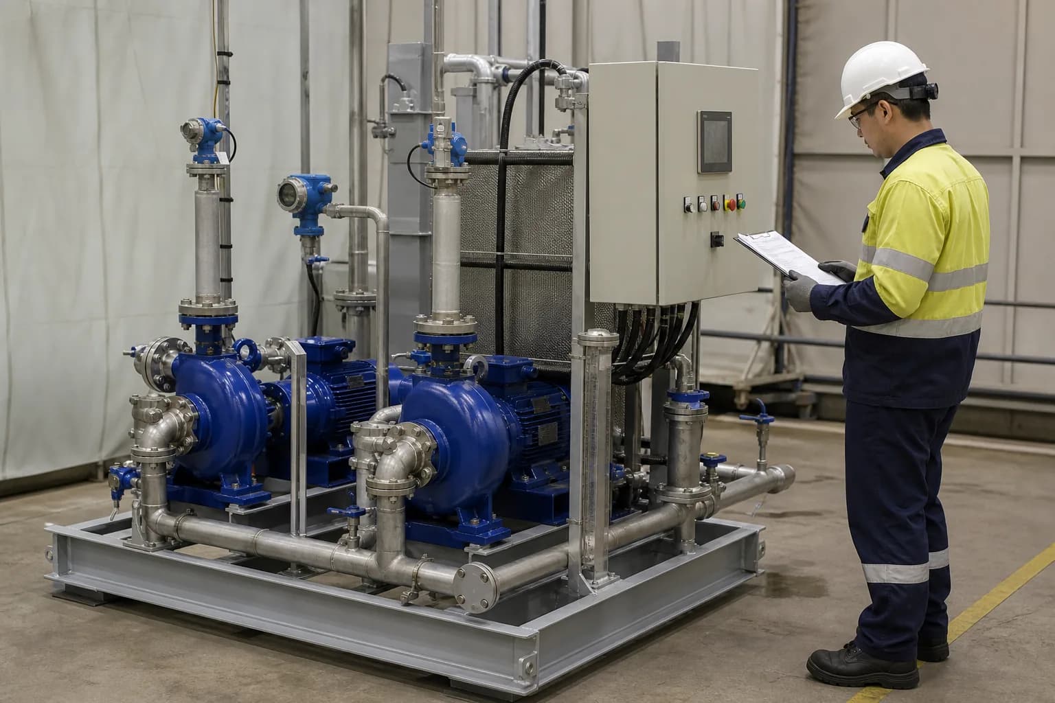
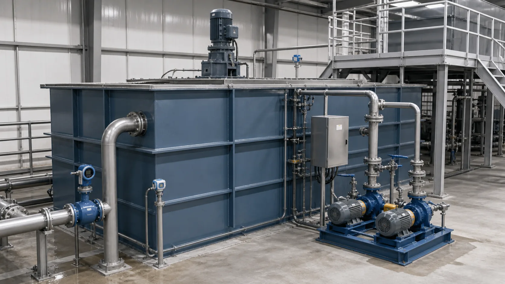
The outflow system should turn the tank volume into a stable downstream feed. A typical scope may include duty and standby pumps, variable-frequency drives, level measurement, independent high-high level protection, low-level pump protection, flow measurement and alarms.
Important control questions include:
- Does the pump maintain the required flow across the full operating head range?
- What happens if the flowmeter signal fails?
- Is high-high level linked to an actionable response, such as stopping an upstream transfer or diverting to defined storage?
- Can the operator see tank level, outlet flow, alarms and pump status?
- Is there a safe mode for maintenance, cleaning and manual operation?
- Are pH or conductivity measurements located where the water is sufficiently mixed to be representative?
Factory testing should confirm the agreed control sequence, alarms, interlocks, rotation and instrument signals. It cannot reproduce the final wastewater behavior unless a project-specific wet test is included.
Common Sizing Mistakes
Using a Fixed Retention Time Without a Flow Balance
Rules such as “eight hours of storage” may be useful for an early screening estimate, but they do not show whether the tank absorbs the actual peak. Use the time-based profile for final sizing.
Combining Incompatible Streams Too Early
Mixing acidic and alkaline water may look beneficial, but it can also cause heat, gas release or uncontrolled precipitation. Cyanide-, sulfide-, chromium- or solvent-bearing streams can require segregation and dedicated safeguards. Confirm compatibility before combining.
Counting Emergency Storage as Normal Working Volume
If operators routinely use the contingency volume, it is not contingency volume. Maintain clear normal low and high levels and verify that alarms leave response time.
Ignoring Solids and Cleaning
Settled solids reduce effective volume and can become difficult to remove. Provide drainability, access and a realistic cleaning method.
Specifying Only Tank Capacity
A tank without suitable mixing, pumping, instrumentation and control logic does not deliver reliable equalization. Evaluate the complete functional package.
Information to Include in an RFQ
Provide suppliers with:
- source and description of every incoming stream;
- at least hourly flow data for representative and peak days where available;
- batch volumes, timing and discharge duration;
- water analyses linked to the relevant operating conditions;
- downstream process and permissible feed range;
- operating hours and planned shutdown periods;
- available site space, elevation and hydraulic constraints;
- tank material expectations and chemical exposure;
- solids, fibers, oil, foam, odor or volatile-compound concerns;
- electrical standard, controls interface and alarm philosophy;
- required redundancy, cleaning and maintenance access;
- defined normal, contingency and emergency duties.
Ask each supplier to state assumptions, total volume, usable working volume, control levels, mixer basis, pump duty point, instrument list and exclusions. This makes quotations easier to compare on a like-for-like basis.
FAQ
How many hours of equalization does industrial wastewater need?
There is no universal number. The required storage depends on the cumulative difference between inflow and controlled outflow, plus load peaks, operating reserve and usable tank geometry. A fixed retention time is only an early estimate unless verified against a representative flow profile.
Can the equalization tank also neutralize pH?
Blending can reduce some pH variation, but it does not replace controlled neutralization when acid or alkali loads are significant. Stream compatibility, heat release, precipitation, gas formation, reagent dosing and control response must be assessed.
Does an equalization tank need aeration?
It needs effective mixing; aeration is one possible method. Mechanical mixing or pumped recirculation may be more appropriate where oxygen transfer, aerosols or volatile compounds are concerns.
Should there be two equalization tanks?
Two compartments or tanks may improve maintenance flexibility, segregation or reliability, but they add valves, controls, mixing equipment and cost. The decision should follow the required availability and operating strategy.
What data are most important for sizing?
Time-based inflow, batch events, downstream feed capacity and the pollutant loads that can limit treatment are the most important. Tank geometry, control levels, mixing and cleaning allowance then convert the hydraulic result into an equipment specification.
Conclusion
Reliable equalization begins with the plant schedule and a time-based flow balance. Calculate the storage created by the difference between inflow and controlled treatment, then test the result against contaminant loads, tank geometry, mixing, pumps, controls and operating contingencies. The deliverable should be a complete functional scope—not merely a nominal tank capacity.
Send your flow profile, batch schedule, water analysis and downstream treatment capacity to request a project-specific equalization review.