Introduction
An industrial wastewater treatment system can be correctly fabricated and still arrive at a site that is not ready to receive it. A doorway may be too small. Anchor bolts may not match the final frame. Drainage may flow in the wrong direction. Electrical capacity may be available, but not at the voltage, frequency, or protection arrangement stated in the approved documents. Process water, compressed air, chemical storage, or crane access may remain unresolved.
These are not minor construction details. They determine whether equipment can be positioned, connected, tested, commissioned, and maintained safely.
International projects add further coordination: packing dimensions, shipment sequence, local civil contractors, different electrical practices, translated documents, remote technical support, customs timing, and the division between supplier supervision and site labor. The most effective control is a written interface checklist maintained from design approval through site acceptance.
This guide gives buyers, engineering contractors, and project teams a practical framework. It does not replace project drawings, local codes, structural calculations, or qualified site supervision.
Start With a Responsibility and Interface Matrix
Before civil work or equipment fabrication begins, identify who is responsible for every project boundary. At minimum, clarify:
- process design and approved design basis;
- detailed equipment design;
- civil and structural design;
- foundations, pits, buildings, and access openings;
- equipment supply and loose accessories;
- off-skid pipework and valves;
- incoming power and site distribution;
- control signals and connection to the customer’s system;
- water, air, steam, cooling, ventilation, and drainage;
- chemical storage and transfer;
- unloading, lifting, positioning, and anchoring;
- installation labor and tools;
- commissioning chemicals, seed sludge, filters, membranes, or consumables;
- performance sampling and laboratory analysis;
- training, handover, and final acceptance.
Each line should name a responsible party, deliverable, required date, and approval status. “By others” is not enough unless the responsible party and technical requirement are visible.
Freeze the Approved Layout Before Foundations
The general arrangement drawing links the treatment process to the real site. It should show equipment orientation, maintenance space, platforms, pipe corridors, cable routes, chemical areas, operator access, drains, sampling points, and major connection locations.
Before using it for construction, confirm:
- revision number and approval status;
- finished floor levels and reference coordinates;
- equipment dimensions and operating clearances;
- door, gate, roof, and access-opening sizes;
- lifting and future replacement routes;
- location of pits, trenches, sumps, and drains;
- available headroom for tanks, columns, membranes, mixers, and cranes;
- separation from production, traffic, hygiene, and hazardous areas;
- space for chemicals, sludge removal, spare parts, and operator work;
- possibility of future expansion only where it is genuinely required.
A layout used for pricing may not contain enough information for construction. Mark preliminary drawings clearly and prevent site teams from building against an unapproved revision.
Civil Works and Foundation Checklist
Civil design must be completed by qualified parties using project-specific loads and local requirements. The equipment supplier should provide relevant interface data, which may include:
- empty, operating, test, and maintenance weights where applicable;
- support and base-frame dimensions;
- static and dynamic load information available for the equipment;
- anchor-bolt or embedded-plate requirements;
- nozzle and connection locations;
- vibration considerations for rotating equipment;
- pit, trench, curb, and bund interface requirements;
- minimum access needed for installation and service.
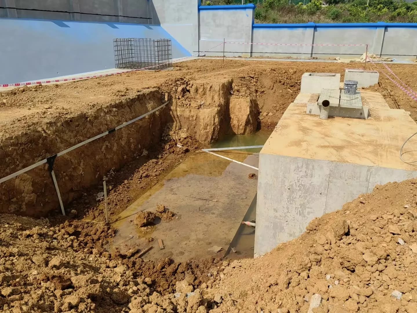
The site team should verify soil and structural conditions, reinforcement, concrete strength, waterproofing, level, flatness, drainage slope, embedded items, and curing status. Do not position equipment on a foundation merely because the concrete surface looks complete.
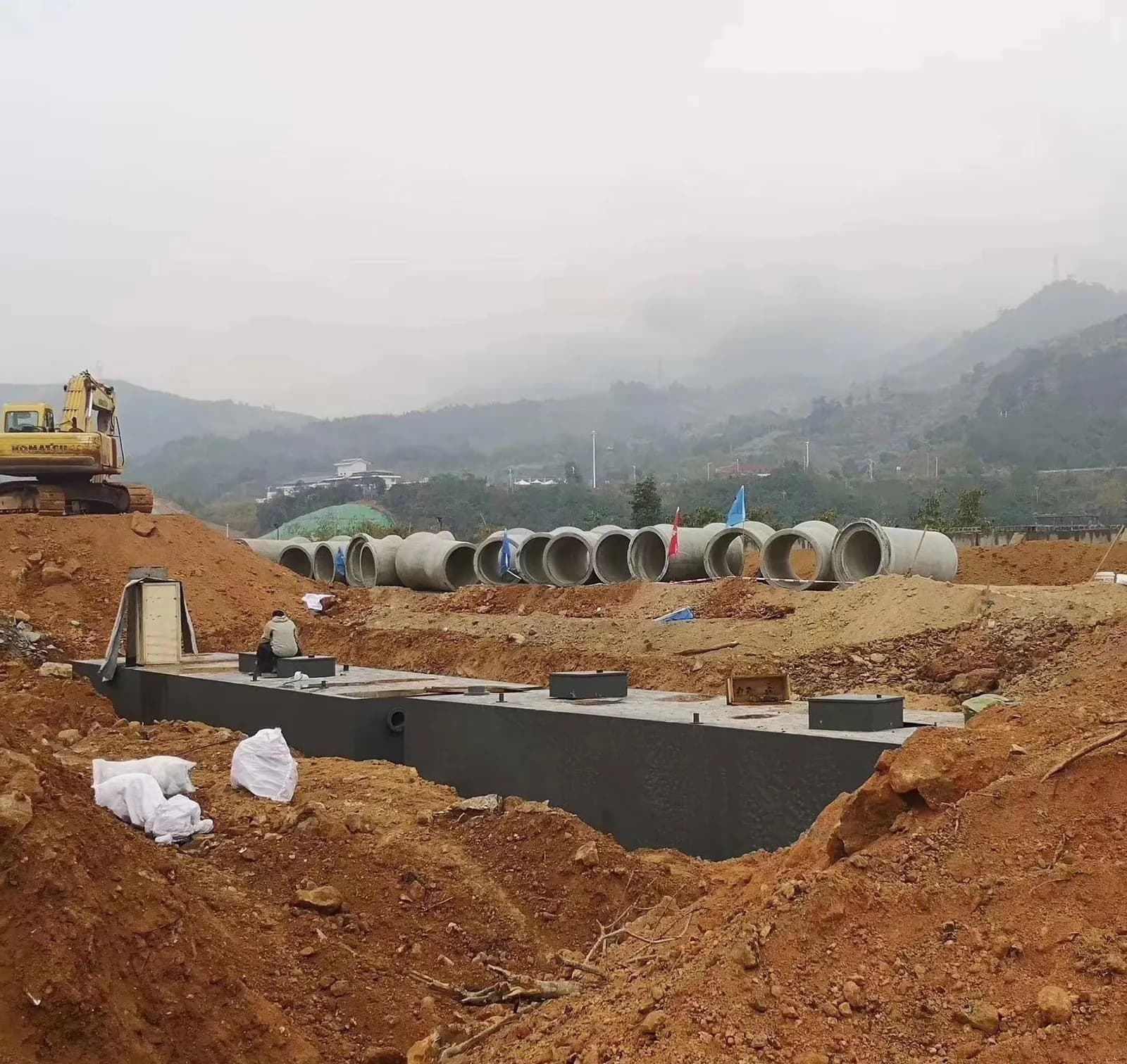
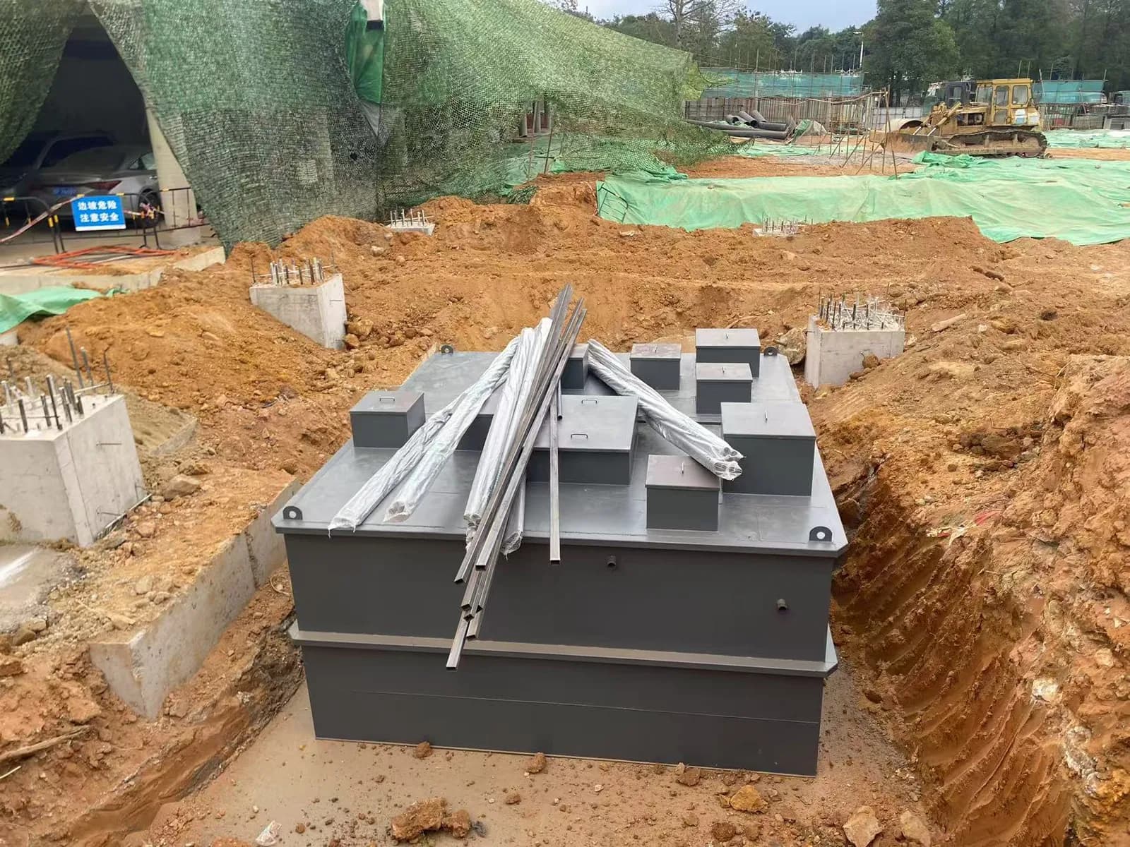
For buried or partially buried tanks, review groundwater, flotation risk, waterproofing, external loads, backfilling method, access covers, confined-space considerations, and future cleaning. These items require professional local design.
Access, Unloading, and Lifting
The delivery route must be checked from the port or site gate to the final foundation—not only to the project boundary. Record:
- packed dimensions and weights;
- container or truck type;
- site gate, road width, turning radius, slope, and overhead clearance;
- floor and road load capacity;
- crane position, reach, capacity, and ground condition;
- lifting points and approved rigging arrangement;
- weather or operating restrictions;
- temporary storage and protection requirements;
- order in which equipment must be unloaded and installed.
Large tanks, evaporator modules, skids, and containers may require different lifting plans. Never use process nozzles, handrails, pipework, or unapproved frame members as lifting points. The local lifting plan should be prepared and supervised by qualified personnel.
Mechanical Installation Checks
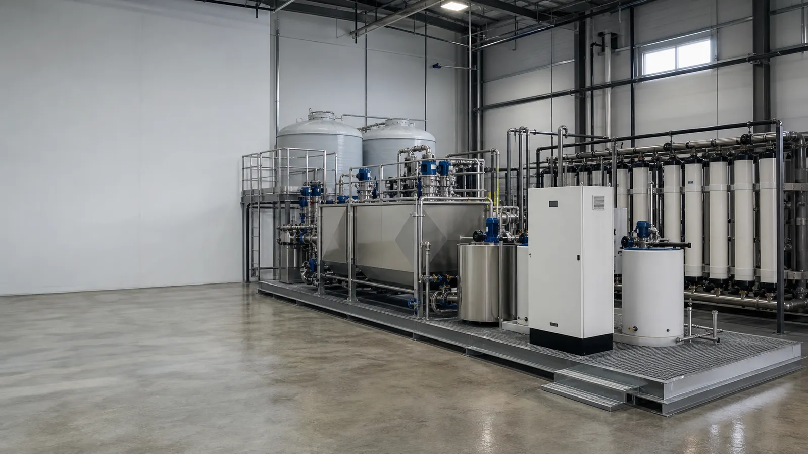
After positioning, the installer should verify orientation, level, alignment, anchoring, and access before permanent connections are completed. Typical checks include:
- equipment tag matches the approved layout;
- supports are complete and correctly placed;
- rotating equipment alignment follows manufacturer instructions;
- temporary shipping braces are removed only when authorized;
- flexible connections are installed without forced misalignment;
- pipework does not impose unintended loads on equipment nozzles;
- valves, strainers, flowmeters, and instruments remain accessible;
- high points, low points, vents, drains, and sampling points are correctly arranged;
- gaskets, bolts, materials, and pressure ratings match the approved specification;
- clean systems are protected from construction debris.
Before hydrostatic, leakage, flushing, or pressure checks, agree the test medium, pressure, duration, isolation boundary, disposal route, and documentation. Some equipment cannot be tested in the same way as site pipework.
Utility Readiness
“Utility available” is not a complete confirmation. The commissioning team needs the utility at the correct connection, quality, pressure, temperature, and capacity.
Incoming Water
Confirm source, analysis where relevant, pressure, flow, connection size, and availability during commissioning. Utility water used for flushing or initial testing may have different quality requirements from process feed water.
Electrical Power
Confirm voltage, frequency, phases, earthing arrangement, available load, protection, short-circuit information where required, cable termination boundary, and local electrical standard. Equipment should not be energized until inspections, insulation checks, protective devices, and safety procedures are complete.
Compressed Air
Confirm pressure, flow, air quality, dew point where relevant, connection, and whether the supply is continuous. Instrument air and general workshop air are not always interchangeable.
Steam, Cooling Water, or Heat-Rejection Utilities
Evaporation and thermal systems may require site-specific steam, condensate, cooling water, ventilation, or heat-rejection data. Confirm supply and return conditions and who provides control valves, traps, meters, and off-skid connections.
Drainage and Waste Routes
Identify normal drains, cleaning drains, emergency overflow, bund drainage, sludge drainage, reject streams, and commissioning water. Do not assume they can all be returned to the same inlet without hydraulic and chemical review.
Electrical, Instrumentation, and Control Interfaces
An electrical interface package commonly includes:
- single-line diagram;
- load list;
- cable schedule;
- motor and instrument list;
- I/O list;
- terminal plan or connection drawing;
- control narrative or sequence description;
- alarm and interlock list;
- communication protocol and data-point scope;
- network, cybersecurity, and remote-access rules where applicable.
Confirm which cables are prewired within the skid and which are installed at site. If the treatment system communicates with a customer PLC, DCS, SCADA, or building system, freeze the interface before software testing.
Loop checks should connect the field device, wiring, control panel, displayed value, alarm, and final control action. A sensor reading correctly on the screen is not enough if the associated interlock or valve response has not been tested.
Chemical Storage and Dosing Areas
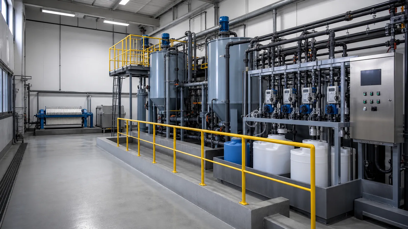
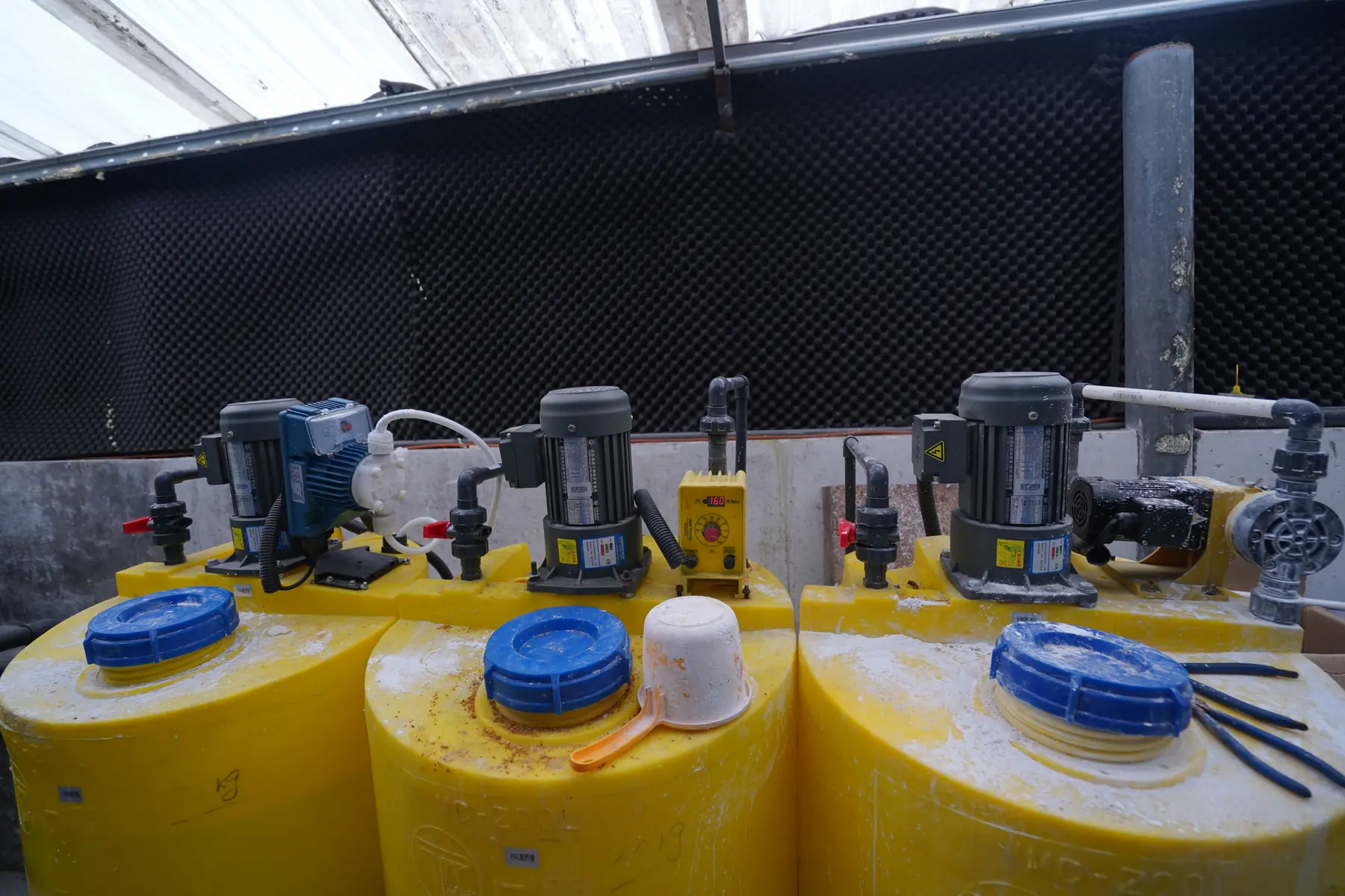
Chemical requirements depend on the process and local safety rules. The project team should review chemical identity, concentration, delivery method, storage volume, compatibility, bunding, ventilation, transfer pumps, dosing points, eyewash or emergency facilities, labeling, and operator handling.
Chemical tanks and pipework must be protected from vehicle impact and incompatible spills. Confirm whether initial chemicals and calibration solutions are supplied with the equipment, sourced locally, or excluded from the contract.
Sludge and Residuals Handling
Commissioning cannot proceed reliably if sludge and residual routes are unfinished. Confirm:
- sludge transfer and storage;
- dewatering equipment and polymer preparation;
- filtrate or centrate return;
- screenings, spent media, concentrate, and chemical containers;
- access for bins, trucks, lifting, and cleaning;
- local disposal or recovery arrangements.
The supplier can define equipment interfaces. Waste classification, transportation, and final disposal must be confirmed with the buyer and relevant local parties.
Factory Acceptance, Shipment Inspection, and Site Receipt
A factory acceptance test should verify the agreed factory-test scope before packing. It may include document review, configuration checks, control-panel tests, alarms and interlocks, dry or clean-water functional checks where suitable, and recording of open items.
Shipment inspection should verify:
- tags and packing list;
- loose components and accessories;
- preservation, caps, and weather protection;
- spare parts and consumables in scope;
- lifting marks and centre-of-gravity information where required;
- document package and packing photos;
- unresolved items and agreed closure action.
At site receipt, inspect external damage, water ingress, broken packaging, missing items, preservation condition, and storage instructions. Record discrepancies before equipment is moved or unpacked beyond what is needed for inspection.
A Controlled Commissioning Sequence
Commissioning should move from safe mechanical completion to controlled process loading. A practical sequence may include:
1. Documentation Review
Confirm approved drawings, manuals, test records, material or calibration documents in scope, punch list, and revision status.
2. Mechanical Completion
Verify equipment installation, supports, guards, lubrication, alignment, valve line-up, pipework completion, drains, vents, and removal of construction debris.
3. Electrical and Instrument Completion
Perform electrical safety checks, energize by approved procedure, verify rotation where appropriate, calibrate instruments, and complete I/O and loop checks.
4. Flushing and Clean-Water Functional Tests
Flush applicable lines, check leakage, operate pumps and valves within safe conditions, verify tank levels, alarms, interlocks, automatic sequences, and emergency stops. Clean-water testing does not prove treatment performance.
5. Chemical and Process Preparation
Prepare chemicals, media, membranes, biological seed, or other process items according to the approved plan. Confirm operator safety and residual disposal.
6. Gradual Introduction of Real Wastewater
Start with controlled loading. Track flow, key water-quality indicators, chemical dose, sludge behavior, biological condition where applicable, equipment current, pressure, level, and alarms. Avoid declaring stable performance from a brief startup period.
7. Optimization and Acceptance Testing
Acceptance should follow the contract: sampling point, test duration, production condition, influent range, laboratory method, exclusions, operator responsibilities, and response to abnormal feed. Performance testing should begin only after prerequisites are met.
The Installation Punch List
A punch list is a control tool, not evidence of failure. Record each item with description, location, responsible party, priority, target date, and closure evidence. Separate safety-critical or commissioning-blocking items from cosmetic or documentation items.
Typical blocking items include missing guards, incomplete electrical protection, leaking chemical lines, unavailable drainage, unverified interlocks, incomplete structural supports, or utilities outside the approved range.
Handover Documents Buyers Should Request
The final package depends on contract scope, but buyers commonly require:
- as-built general arrangement and process drawings;
- piping and instrumentation diagrams;
- electrical drawings and I/O records;
- equipment, valve, instrument, and motor lists;
- operation and maintenance manuals;
- spare-parts and consumables lists;
- factory and site test records;
- calibration or material documents included in scope;
- commissioning settings and final punch-list status;
- training record and maintenance schedule;
- warranty boundary and support contacts.
Confirm file format, language, quantity, and handover date before shipment. Documents are easier to complete while project details are still active.
FAQ
When should site preparation begin?
Site planning can begin during detailed design, but construction should use approved interface drawings and qualified local civil design. Foundations should not be built from preliminary quotation layouts.
Who is responsible for the foundation design?
The contract should state the boundary. The equipment supplier normally provides available equipment loads and interface information; qualified local structural professionals design and approve the foundation under local conditions and requirements.
What must be ready before equipment arrives?
The delivery route, lifting plan, foundation, access opening, temporary storage, utilities needed for installation, receiving inspection process, and responsible site personnel should be confirmed. The exact readiness list depends on shipment sequence.
Is factory acceptance the same as site acceptance?
No. Factory acceptance verifies the agreed factory scope before shipment. Site acceptance verifies installation, utilities, functions, and—if included—process performance under defined site conditions.
Can the system be commissioned with clean water only?
Clean water is useful for flushing, leakage checks, instruments, pumps, valves, alarms, and sequence testing. It cannot confirm final treatment performance with real industrial wastewater.
What information helps a supplier prepare installation documents?
Provide the site plan, floor levels, local utility data, electrical standard, access constraints, civil boundary, interconnecting pipe and cable responsibility, discharge or reuse point, and the customer’s document requirements.
Conclusion
Successful installation is the result of controlled interfaces. Approved drawings, civil readiness, access, utilities, mechanical and electrical completion, residuals handling, documentation, and acceptance responsibilities must align before real wastewater is introduced.
The most useful project habit is to keep one live responsibility matrix and one controlled punch list. They make assumptions visible, prevent tasks from falling between supplier and contractor, and give commissioning teams a reliable basis for safe startup.
Send Your Requirements
If you are preparing the installation of an industrial wastewater treatment system, send Baihuipu your equipment scope, site layout, utility data, construction status, and project schedule. Our team can review the information needed for equipment interfaces, factory inspection, shipment preparation, and commissioning coordination.