Introduction
Fluoride-bearing wastewater can come from semiconductor etching and cleaning, printed-circuit-board processes, aluminum finishing, glass treatment, photovoltaic and battery manufacturing, mineral processing and chemical production. The source matters because “fluoride” on a laboratory report may represent different chemical conditions.
Free fluoride, hydrofluoric-acid-bearing water, fluosilicate, ammonium fluoride and metal-fluoride complexes do not necessarily respond identically. Aluminum, silicon, phosphate, sulfate, ammonia, alkalinity and dissolved salts can change calcium demand, precipitation behavior and polishing performance.
The U.S. EPA’s technical documents for electrical and electronic components describe calcium-based precipitation followed by solids removal as a widely used fluoride-treatment route. They also note that actual industrial performance depends on wastewater characteristics rather than theoretical calcium-fluoride solubility alone. See the EPA Electrical and Electronic Components study and the historical development document.
This guide focuses on procurement decisions: when precipitation is the main process, when polishing deserves evaluation and what data should be in the RFQ.
Why Fluoride Treatment Is Often a Two-Objective Problem
Most projects contain two different duties:
- Bulk removal: reduce a high fluoride load economically and reliably.
- Polishing: reach a lower discharge or reuse target after the bulk load has been removed.
Calcium precipitation can be practical for bulk removal because calcium reacts with fluoride to form low-solubility calcium fluoride. In real wastewater, however, reaction kinetics, calcium availability, complexes, ionic strength, particle size and separation performance can leave a residual higher than a theoretical calculation suggests.
Trying to achieve an extremely low outlet by adding unlimited lime can increase sludge, scaling and chemical carryover without delivering a stable result. Conversely, sending high-fluoride raw water directly to adsorption media, ion exchange or reverse osmosis can consume media rapidly, scale membranes or create a difficult concentrate.
The treatment train should assign each technology a realistic duty.
Begin with a Fluoride Source Map
List each fluoride-bearing and non-fluoride stream separately before selecting tanks. Possible sources include:
- hydrofluoric acid or buffered-oxide-etch rinse water;
- ammonium fluoride or ammonium bifluoride processes;
- glass or silicon etching and cleaning;
- aluminum etching, anodizing or fluoride-containing sealing;
- scrubber blowdown;
- concentrated bath dumps and dilute cascade rinses;
- regeneration waste from a polishing unit;
- relatively clean UPW reject, cooling water or non-contact water.
For every stream, record average flow, peak hourly flow, batch volume, release schedule, fluoride concentration, pH, temperature and the production chemistry entering the drain.
Source segregation can keep a concentrated dump from controlling the whole plant and prevent low-load reusable water from being unnecessarily contaminated. It can also allow strong fluoride waste to be batch treated or metered into a continuous system at a controlled rate.
Analytical Data Needed for a Reliable Design
Fluoride concentration is essential, but it is not a complete basis. The following can influence treatment:
- total fluoride and, where relevant, dissolved or free-fluoride interpretation;
- pH, alkalinity and acidity;
- calcium, magnesium, aluminum and silicon;
- phosphate, sulfate, chloride and nitrate;
- ammonia and ammonium salts;
- conductivity and TDS;
- suspended solids and turbidity;
- COD or TOC when organics may interfere with adsorption or membranes;
- metals that may precipitate in the same pH range;
- flow, batch schedule and target destination.
Attach the original laboratory report and identify the sampling point. Composite wastewater collected after uncontrolled mixing can hide the strongest source and make chemical demand appear more stable than it is.
The outlet requirement should name the receiving point: municipal sewer, industrial-park plant, surface discharge, internal rinse reuse, cooling-tower makeup or another process. The applicable limit and analytical method must be confirmed locally. No global fluoride target can be assumed from an unrelated project.
Option 1: Calcium-Based Precipitation for Bulk Fluoride Removal
How the process works
A calcium source—commonly lime, calcium chloride or a tested combination—provides calcium ions that react with fluoride to form calcium fluoride solids. The process then requires particle growth and separation:
- equalize or meter the fluoride load;
- adjust pH and add the selected calcium reagent;
- provide reaction time and mixing;
- add coagulant or flocculant where testing shows a benefit;
- clarify or otherwise separate the calcium-fluoride solids;
- filter if fine-particle carryover controls the result;
- dewater and manage the resulting sludge.
The reaction is simple on paper, but equipment must handle slurry, scaling and fine precipitate. Lime systems need reliable powder or slurry preparation, agitation and line-flushing provisions. Calcium chloride is more soluble but changes chemical cost, chloride load and storage requirements.
Why pH and calcium dose must be tested together
Calcium availability and fluoride speciation change with pH. Aluminum can form fluoride complexes, while phosphate and sulfate can consume calcium or create additional solids. A stoichiometric dose calculated from one fluoride value may therefore be inadequate or wasteful.
A useful test matrix compares pH, calcium-to-fluoride dose, reagent sequence, reaction time, coagulant, polymer and settling behavior. Measure fluoride after an agreed filtration condition so dissolved residual is not confused with fine calcium-fluoride particles.
Why solids separation matters
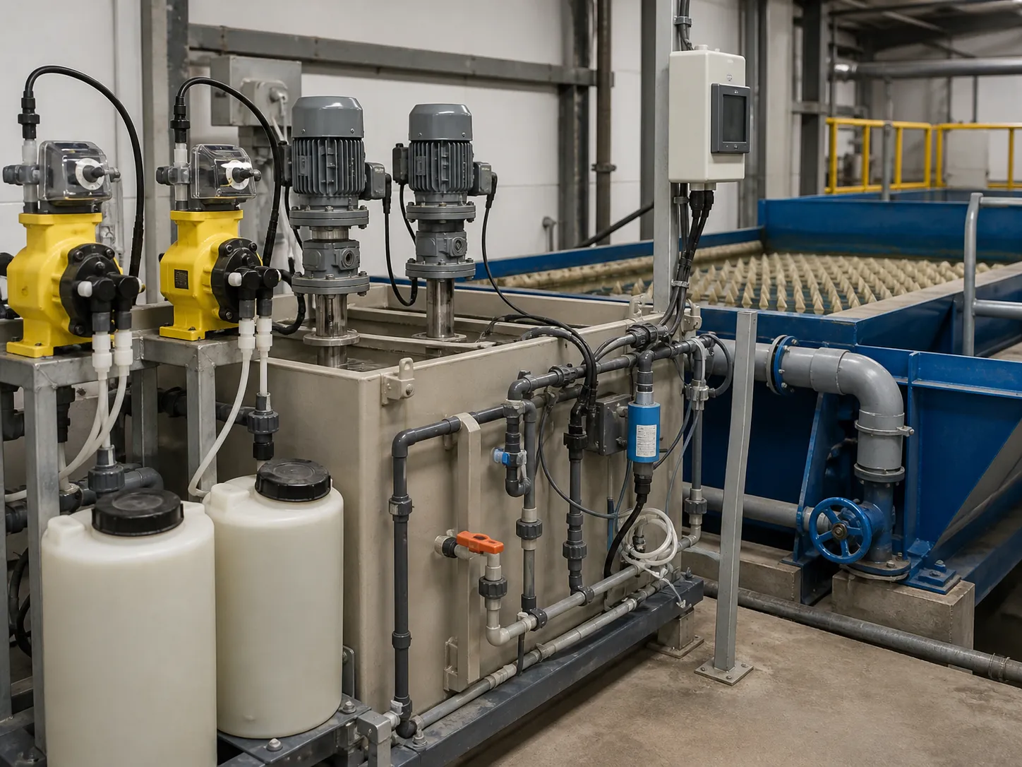
Calcium-fluoride precipitate can be fine. Poor flocculation or hydraulic overloading can cause particulate fluoride to escape a clarifier even when the chemical reaction is adequate. The separator should be selected using observed floc behavior, hydraulic loading, sludge recycle where applicable and the need for downstream filtration.
The EPA’s referenced semiconductor study describes calcium-salt precipitation and coagulation/flocculation as connected functions. This is a practical reminder that a reaction tank alone is not a complete fluoride-removal system.
Option 2: Adsorption for Fluoride Polishing
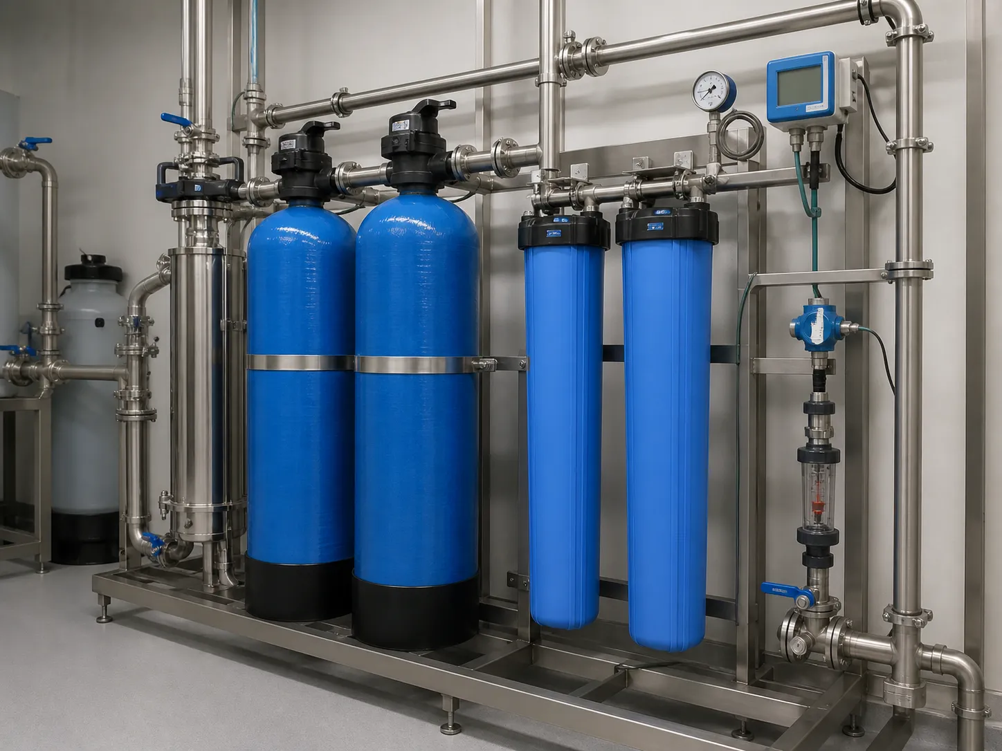
Activated alumina and other fluoride-selective media can be evaluated when a lower residual is required after bulk precipitation. Adsorption can be useful for a controlled, relatively low-solids feed, but capacity depends on pH, competing ions, alkalinity and the actual media.
The procurement review should address:
- influent fluoride range after pretreatment;
- suspended-solids and turbidity limit;
- competing sulfate, phosphate, silica and alkalinity;
- target breakthrough concentration;
- empty-bed contact time and vessel arrangement;
- media capacity based on representative water;
- regeneration or single-use replacement strategy;
- regenerant wastewater destination;
- lead-lag operation and sampling points.
Vendor literature capacity measured in clean laboratory water should not be used as the only design value. A pilot column or representative-water test can reveal capacity loss and breakthrough behavior.
Option 3: Ion Exchange
Specialty anion-exchange or fluoride-selective resins may be considered for polishing or recovery-oriented applications. As with adsorption, competing anions strongly affect capacity. Pretreatment must protect the resin from suspended solids, oil, oxidants and precipitated calcium salts.
Ion exchange moves fluoride into a regenerant or spent-resin stream. The mass does not disappear. The RFQ should define regeneration chemicals, rinse volume, waste routing, resin replacement and operator responsibilities.
Ion exchange should be compared against adsorption on total lifecycle duty, not just vessel price. Media life, chemical use, regeneration frequency, wastewater volume and required standby capacity can change the result.
Option 4: Membrane Separation
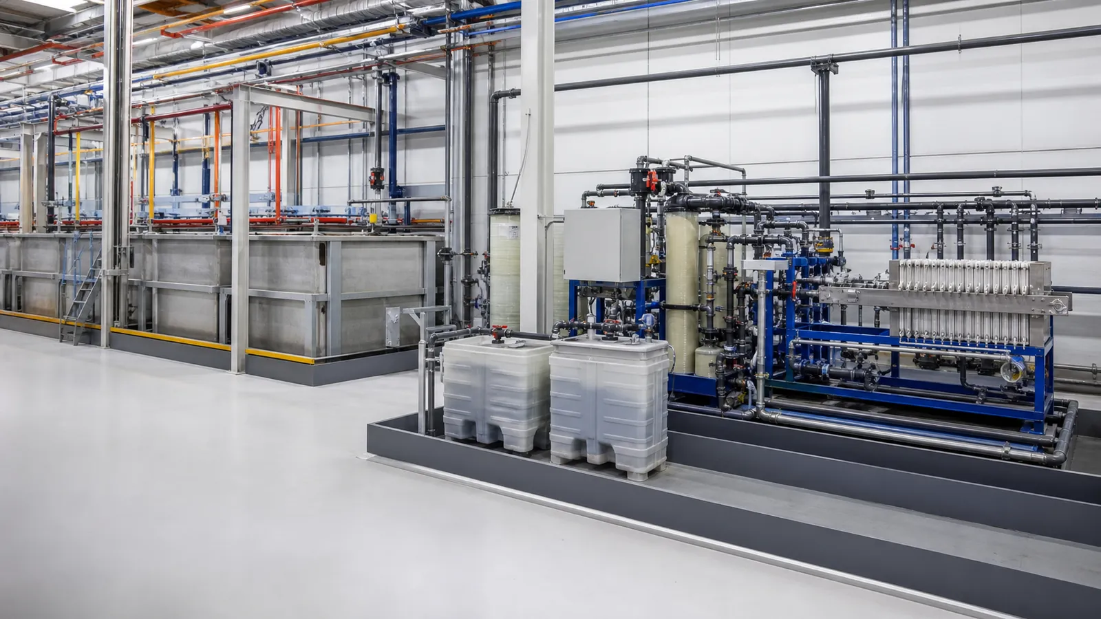
Reverse osmosis or nanofiltration may be evaluated when fluoride control is part of a broader dissolved-salt or water-reuse objective. Membranes do not convert fluoride into a harmless form; they divide the feed into permeate and concentrate.
Before selecting RO, review:
- calcium-fluoride and other scaling risk;
- silica, aluminum, hardness and sulfate;
- residual coagulant, polymer and suspended solids;
- feed pH and membrane compatibility;
- target recovery and concentrate concentration;
- cleaning strategy and chemical compatibility;
- concentrate treatment, evaporation or permitted disposal.
A high recovery selected only to reduce concentrate volume can exceed scaling limits. Pretreatment and recovery should be modeled from the complete water analysis, then verified through pilot or staged testing where uncertainty is material.
How to Compare the Four Options
| Selection factor | Calcium precipitation | Adsorption | Ion exchange | RO / NF |
|---|---|---|---|---|
| Best-fit duty | Bulk removal | Low-load polishing | Selective polishing | Fluoride plus broader salt removal |
| Feed solids tolerance | Moderate with designed separation | Low | Low | Very low |
| Main residual | Calcium-fluoride sludge | Spent or regenerated media | Regenerant or spent resin | Concentrate |
| Key sensitivity | pH, calcium demand, competing ions, floc | pH and competing ions | Competing anions and fouling | Scaling, fouling and recovery |
| Critical test | Jar/treatability test | Media or column test | Resin capacity/breakthrough test | Scaling model and pilot where needed |
This table defines roles, not guaranteed performance. Many reliable systems combine precipitation with one polishing technology rather than choosing only one method.
Bench and Pilot Testing Checklist
For precipitation, record:
- sample source and production condition;
- initial fluoride, pH and relevant competing ions;
- reagent identity, purity and dose;
- sequence, mixing and reaction time;
- final pH and calcium residual where useful;
- coagulant and polymer dose;
- settling rate, sludge volume and filtered fluoride;
- repeatability across representative samples.
For adsorption or ion exchange, record bed volume treated, flow, pH, breakthrough curve, competing-ion profile, regeneration result and waste volume. For membranes, record normalized flux, rejection, pressure, recovery, scaling tendency, cleaning response and concentrate composition.
An attractive clear beaker is not enough. Fluoride analysis and solids behavior are the relevant evidence.
Equipment Specification and Layout
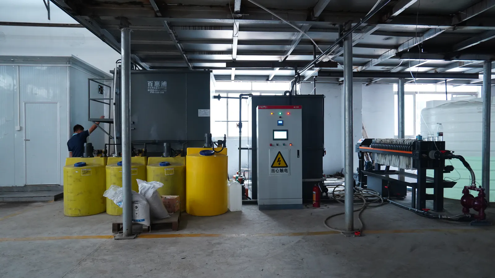
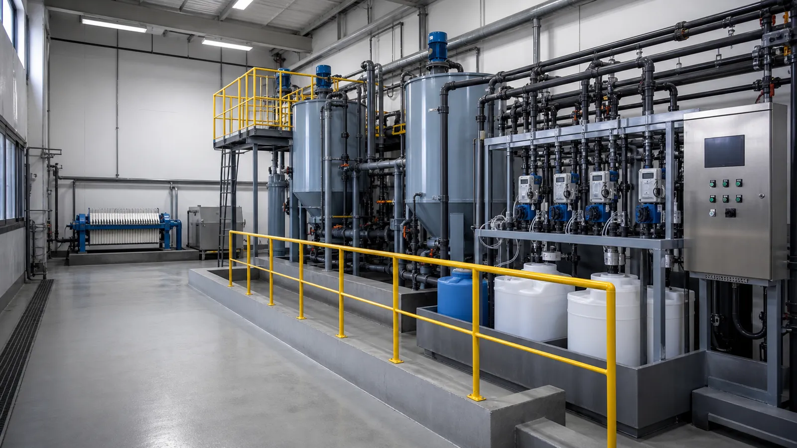
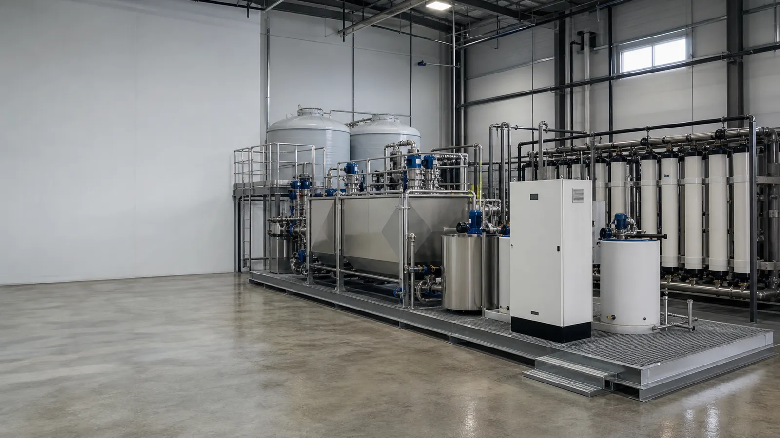
A precipitation-based fluoride system may include separate collection, equalization, reagent preparation, reaction, flocculation, clarification, sludge holding, filtration and dewatering. The exact arrangement should follow test results and site constraints.
Specify:
- average, peak and batch flow;
- tank working volume and retention basis;
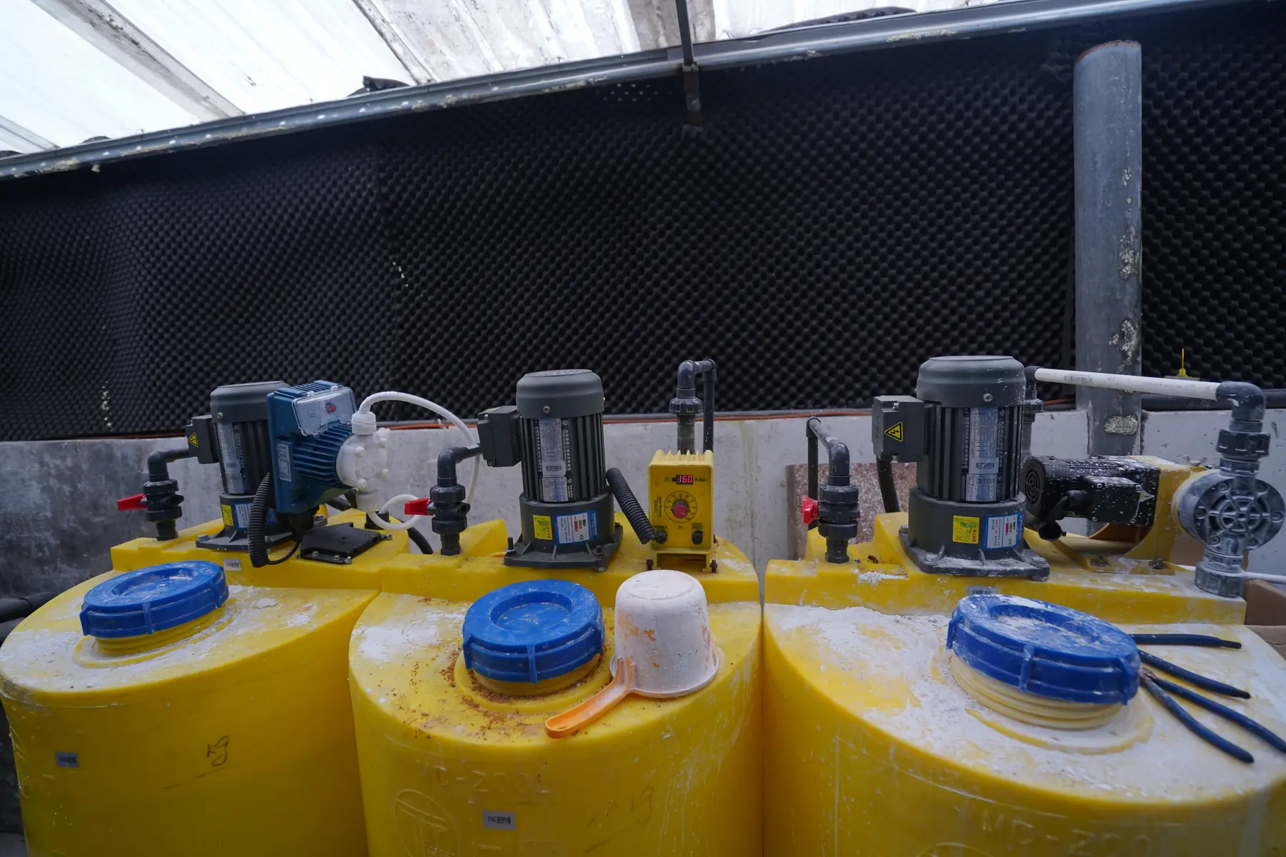
- slurry-compatible pumps, mixers and valves;
- chemical storage, transfer and secondary containment;
- pH instruments and any calcium or fluoride monitoring strategy;
- sample points before and after each critical stage;
- clarifier or flotation loading basis;
- filtration duty and backwash destination;
- sludge production basis and dewatering cycle;
- access for cleaning scaled tanks, probes and pipelines;
- PLC sequences, alarms and data logging;
- ventilation, drainage and operator safety interfaces.
Calcium systems can scale at dosing points, elbows, probes and stagnant lines. Maintenance access and flushing provisions are design requirements, not afterthoughts.
Factory Testing, Installation Preparation and Acceptance
Factory testing can verify tank and skid identity, pump rotation, mixers, valves, instruments, control logic, alarms and clean-water operation. It cannot verify fluoride removal without representative feed and reagents.
Shipment inspection should protect instrument faces, dosing pumps and membrane or media vessels; cap open pipework; label loose items; and document the packing list. Installation preparation should confirm foundations, drains, water, electrical supply, chemical unloading, ventilation, lifting access and sludge-removal route.
Performance acceptance should define:
- influent fluoride and competing-ion envelope;
- required flow and operating schedule;
- reagent specifications and dosing conditions;
- stabilization and test period;
- sampling locations and filtration convention;
- laboratory method and target;
- acceptable sludge and residual-management conditions;
- response to abnormal or out-of-range feed.
If reuse is included, acceptance must also cover the point-of-use water quality and concentrate or regeneration waste.
Common Procurement Mistakes
- Designing from fluoride alone: aluminum, phosphate, calcium and pH can change the reaction.
- Using theoretical solubility as a guarantee: industrial matrices and solids carryover affect actual results.
- Ignoring fine calcium-fluoride solids: clarification and filtration may control the measured outlet.
- Sending raw high-fluoride water directly to polishing media: capacity and replacement cost can become impractical.
- Selecting RO without a concentrate route: fluoride is concentrated, not destroyed.
- Omitting regenerant or spent-media disposal: adsorption and ion exchange create residual streams.
- Ignoring scale access: dosing lines and probes need inspection, flushing and cleaning.
- Calling clear water compliant: fluoride requires laboratory confirmation.
FAQ
What is the most common way to remove high fluoride from industrial wastewater?
Calcium-based precipitation followed by solids separation is widely used for bulk removal. The exact reagent, pH, dose and separation method require representative testing.
Can lime treatment always reach a very low fluoride concentration?
No. Actual residual depends on feed chemistry, calcium availability, complexes, reaction time and separation. A polishing stage may be needed for a lower verified target.
Is calcium chloride better than lime?
Neither is universally better. Calcium chloride is highly soluble; lime can provide both calcium and alkalinity. Chemical cost, chloride addition, slurry handling, sludge and test results should be compared.
Can activated alumina polish fluoride after precipitation?
It may be suitable for a controlled clarified feed. Capacity and breakthrough depend on pH and competing ions, so representative-water or column testing is recommended.
Can RO remove fluoride?
RO may reject fluoride as part of dissolved-salt removal, but scaling, pretreatment, recovery and concentrate management govern feasibility. It is not automatically the best bulk-removal step.
Should high-fluoride streams be segregated?
Often yes. Segregation can keep concentrated batches controllable and protect lower-load water that may be easier to reuse or treat.
Conclusion
Fluoride removal is most reliable when the treatment train separates bulk removal from polishing. Calcium precipitation can convert a large fluoride load into solids; coagulation, flocculation, clarification and dewatering determine whether those solids are actually removed. Adsorption, ion exchange or membranes can then be evaluated for a defined lower residual or reuse objective.
The buyer’s task is to connect source chemistry, water analysis, testing, equipment duty and residual management. A complete RFQ includes fluoride form and range, competing ions, flow timing, outlet destination, sludge or concentrate boundary and an acceptance protocol tied to representative feed.
Send Your Fluoride Water Data
Send the fluoride source, representative analysis, average and peak flow, batch schedule, target, site limitations and destination country. Baihuipu can review the information required for treatability testing and a project-specific fluoride wastewater treatment proposal.
Related resources: