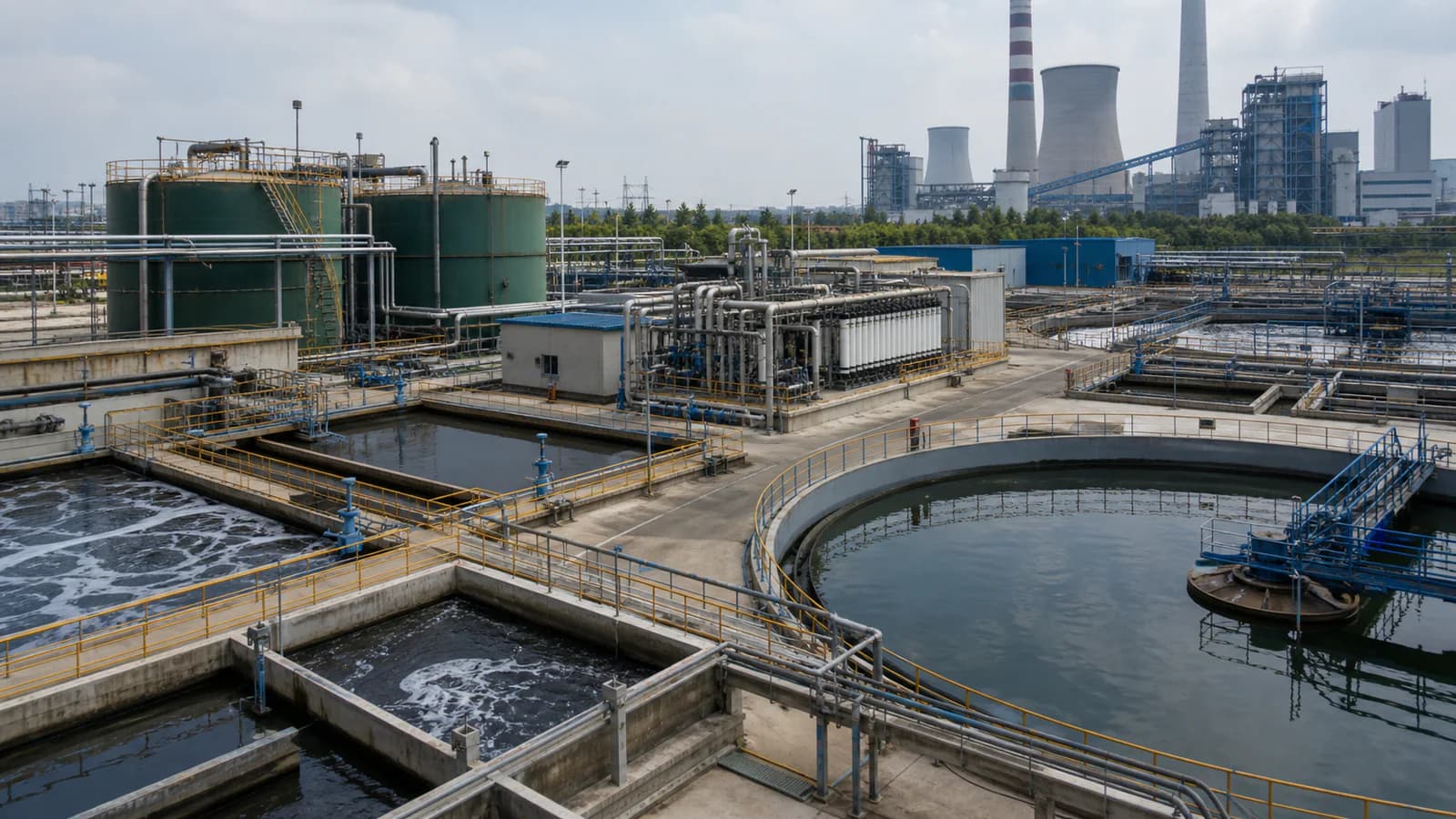
Introduction
FGD wastewater is generated when wet flue-gas-desulfurization systems control sulfur dioxide from combustion gas. Its chemistry is influenced by fuel, limestone or reagent quality, absorber operation, chloride control, oxidation conditions, makeup water, gypsum dewatering, purge strategy and other plant streams.
That combination can produce high dissolved salts, suspended gypsum or fly-ash solids, chloride, sulfate, calcium, magnesium, trace metals and variable selenium or nitrogen species. The water may be warm, corrosive, scaling and chemically inconsistent. A process that performs well on one station’s purge may not transfer directly to another.
The U.S. EPA’s steam-electric technical documents evaluate chemical precipitation, biological treatment, membrane filtration, spray evaporation, brine concentration and crystallization among relevant FGD wastewater options. The important procurement lesson is not that every project needs all of them. It is that each technology has a distinct treatment role and produces a residual that must be managed.
This guide explains how an owner, EPC contractor or procurement team can compare conventional treatment, membrane concentration and thermal ZLD without relying on a generic equipment package. It complements the Power Generation & Energy water-treatment solution and the wastewater evaporator selection path.
First Define the Project Objective
Controlled discharge
A discharge project targets specified parameters at a permit sampling point. The treatment train should be based on the applicable local requirements, not copied from another country’s rule. Some parameters may be controlled by precipitation and solids separation; others may require biological, adsorption, reduction, membrane or another polishing step.
Water reuse and volume reduction
The plant may seek to recover water for scrubber makeup, ash handling, cooling or another defined use while reducing the volume of concentrate. Reuse quality should be set by the receiving process, including chloride, hardness, silica, suspended solids and corrosion or scaling risk.
Zero liquid discharge
ZLD aims to eliminate routine liquid discharge by recovering water and converting the remaining contaminants into a solid or managed residual. It does not eliminate waste. It changes its form. The project still needs routes for pretreatment sludge, membrane concentrate where applicable, crystallized salts or mixed solids, cleaning waste and off-spec liquids.
Compliance upgrade or plant integration
An existing plant may be adding treatment to meet a new requirement, modifying an absorber purge, closing a pond, integrating bottom-ash or leachate streams, or changing the station water balance. Scope definition should identify which streams are included and which remain separate.
What Makes FGD Wastewater Difficult?
High dissolved salts
Chloride, sulfate, calcium, magnesium, sodium and other ions can create high ionic strength, corrosion and scaling. Conductivity or TDS alone is not enough for design; individual ion concentrations and speciation matter.
Supersaturation and scaling
Gypsum, calcium carbonate, magnesium compounds, silica and other salts can precipitate as pH, temperature and concentration change. A process that recovers more water also concentrates scale-forming species. Antiscalant cannot replace a complete saturation and mass-balance assessment.
Suspended and fine solids
Gypsum particles, fly ash and metal precipitates can overload clarifiers or foul membrane systems. Particle size, density, settling and filterability influence the solid–liquid-separation stage.
Trace metals and selenium
Arsenic, mercury, nickel and selenium are among pollutants associated with steam-electric wastewater. Their chemical form affects removal. Selenium can exist in forms that do not respond equally to conventional precipitation, so a project may need a specific reduction, biological or polishing approach.
Variable operation
Coal source, load, absorber chemistry, chloride purge and upstream water management can change the influent. Average data should be supplemented with ranges, trends and upset conditions.
Corrosion and materials
Chloride, temperature, pH and oxidizing conditions can challenge carbon steel, stainless steel, coatings, elastomers and instruments. Material selection must be tied to each process zone rather than applying one material to the entire system.
Stage 1: Conventional Physical-Chemical Treatment
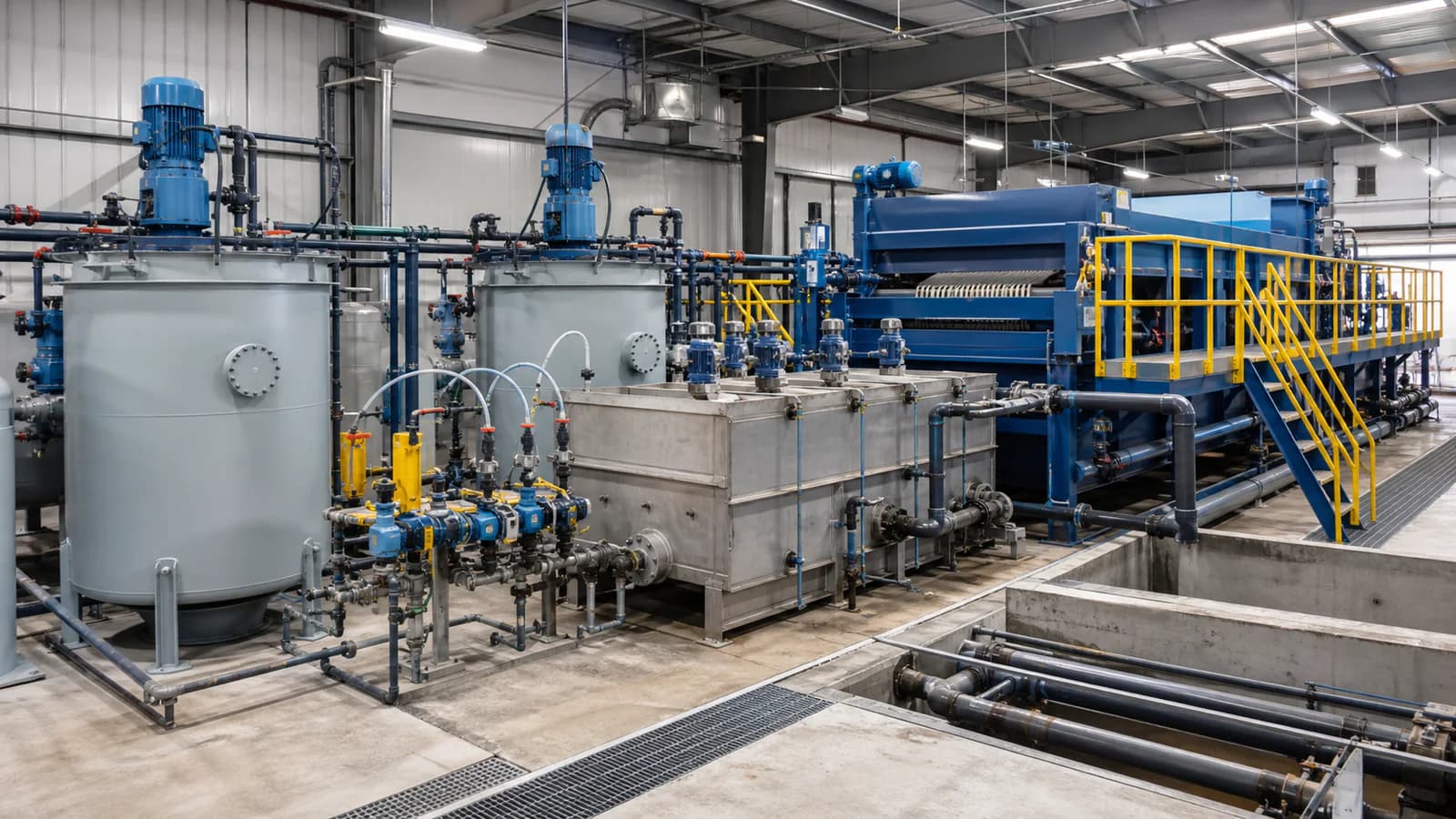
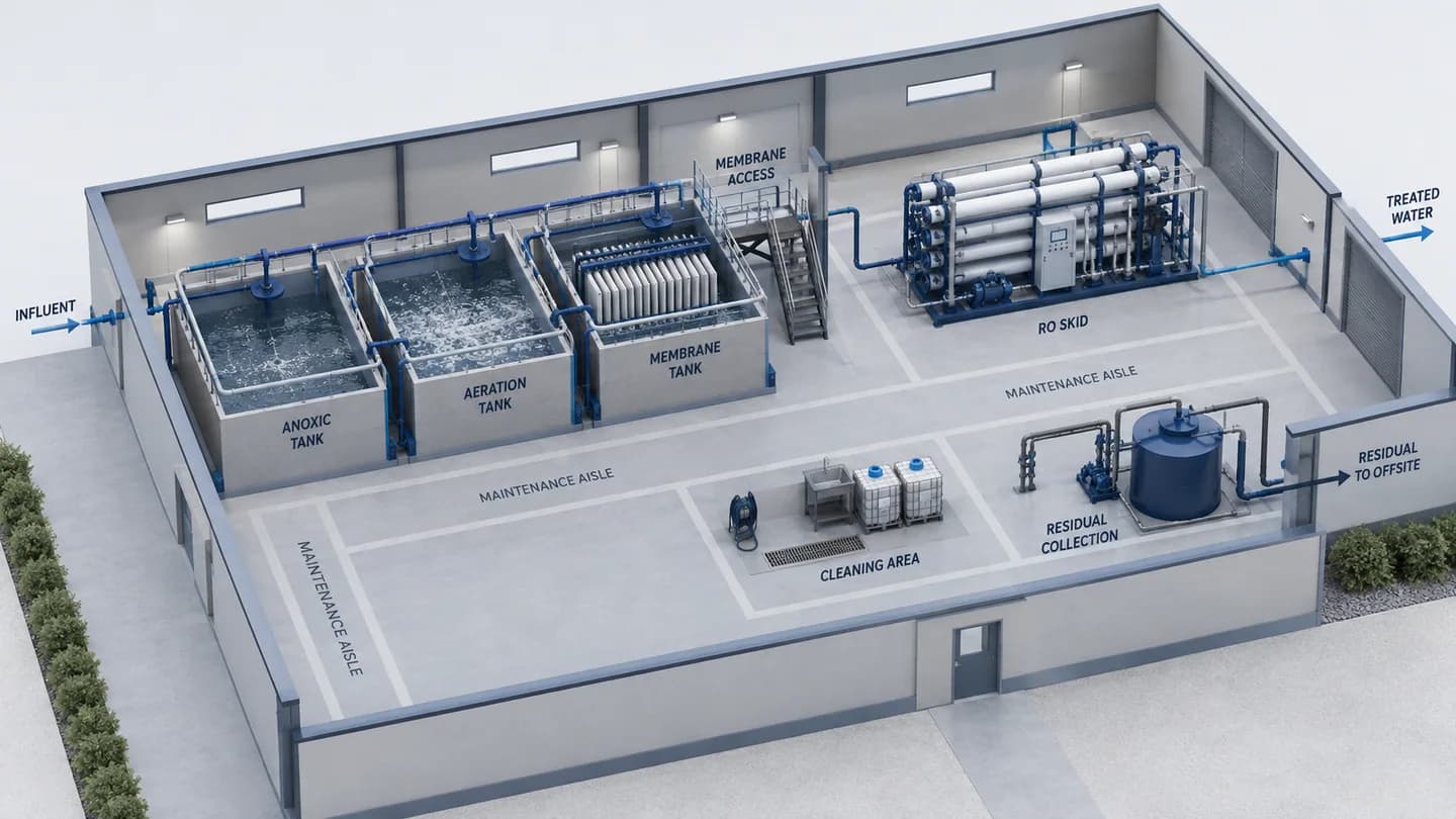
A conventional FGD wastewater train may include equalization, pH adjustment, chemical precipitation, coagulation, flocculation, clarification and sludge dewatering. The exact sequence varies.
Equalization and feed control
Equalization reduces short-term variation and gives operators a controlled feed. Review tank mixing, solids suspension, corrosion, ventilation, level protection, retention time and off-spec storage. If another plant wastewater is proposed for blending, confirm whether it dilutes, reacts with or destabilizes the FGD stream.
Precipitation and co-precipitation
Lime or other alkaline reagents may precipitate metal hydroxides and change the saturation of calcium, magnesium and sulfate species. Iron salts can support co-precipitation or adsorption of certain contaminants. Sulfide reagents may be evaluated for specific metals but require strict chemical and gas-safety controls.
The buyer should request the chemical basis, reaction stages, target pH range, expected sludge and assumptions. “Heavy-metal removal” is not a complete description when speciation and influent variation are unknown.
Coagulation, flocculation and clarification
These stages aggregate fine particles and separate them as sludge. Clarifier loading, floc behavior, recycle, sludge withdrawal and dewatering affect performance. Lamella or other compact separators may reduce footprint but do not remove the need for robust upstream chemistry and downstream sludge handling.
What conventional treatment may not remove
Physical-chemical treatment can be effective for suspended solids and precipitable metals, but may not alone meet a project’s requirement for dissolved salts, nitrate, certain selenium forms, boron or a ZLD objective. The gap between conventional effluent and the final target determines whether polishing is needed.
Stage 2: Biological or Specialty Polishing
Biological systems may be evaluated for nitrate and certain selenium species when wastewater chemistry, temperature, salinity, carbon source and toxicity are suitable. The process needs controlled loading and protection from oxidants or contaminants that inhibit biomass.
Biological treatment produces waste biomass and may require solids separation, nutrient or carbon dosing, temperature control and startup time. It should not be specified simply as “selenium removal” without defining influent species, expected range, target, monitoring and fallback conditions.
Other polishing options may include adsorption media, ion exchange, zero-valent iron or project-specific chemical reduction. Each option has capacity, replacement, regeneration, residual and interference limits. Bench or pilot testing may be needed to compare them using real wastewater.
Stage 3: Membrane Treatment and Concentration
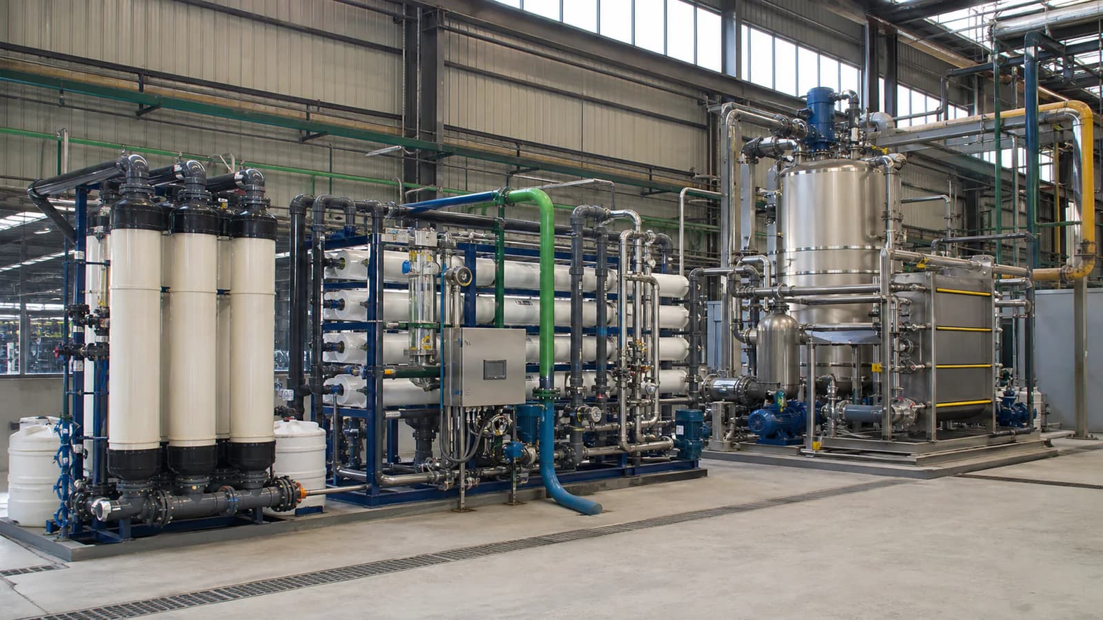
Membranes can be used to recover water and reduce the volume requiring final disposal or evaporation. Depending on the wastewater and objective, the train may include microfiltration or ultrafiltration, nanofiltration, reverse osmosis or specialized configurations.
Pretreatment controls membrane feasibility
Membranes require control of suspended solids, precipitated metals, hardness, sulfate, silica, oxidants and organics. Pretreatment may involve clarification, softening, filtration, pH adjustment and chemical control. Stable operation matters more than a single clean feed test.
Recovery is a mass-balance decision
Higher recovery reduces concentrate flow but increases ion concentration and scaling risk. The design should show feed, permeate and concentrate flows together with major ion balances. Recovery should be tied to temperature, feed chemistry, membrane limits, cleaning and concentrate treatment.
Permeate needs a destination
Membrane permeate may be suitable for a defined plant reuse after checking its quality against that use. It should not be labeled “reusable” without a destination, sampling point and parameter list.
Concentrate remains part of the project
RO concentrate contains the rejected salts and contaminants. It may return to the absorber only if the plant chemistry and chloride balance allow, go to further concentration, enter evaporation, or follow another approved route. An RO skid without a concentrate boundary does not solve the wastewater problem.
Stage 4: Thermal Treatment and ZLD
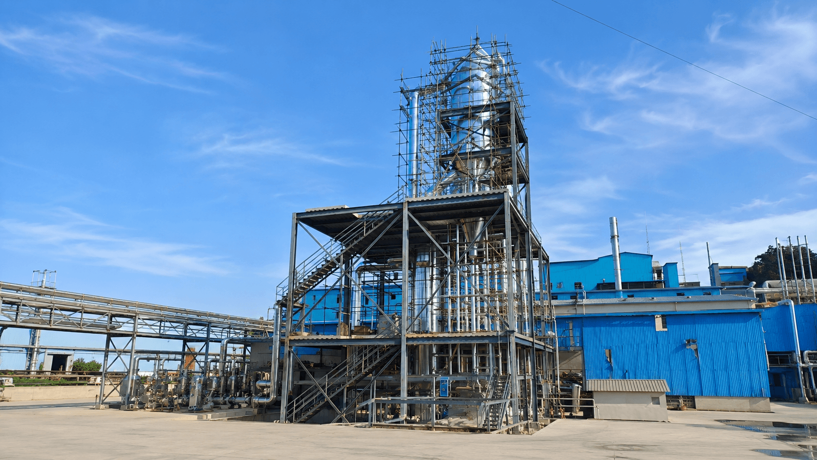
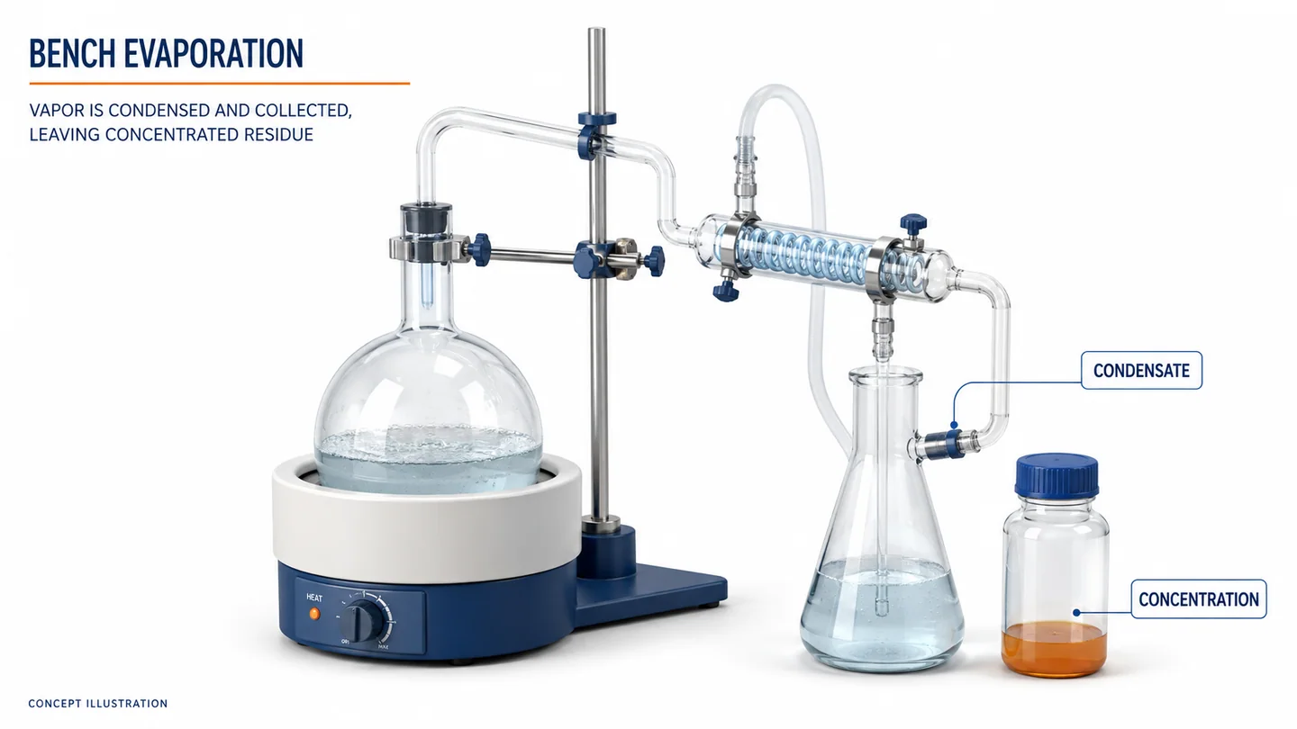
Thermal technologies use heat to evaporate water and concentrate contaminants. Configurations can include multi-effect evaporation, mechanical vapor recompression, brine concentrators, crystallizers, spray evaporation or other project-specific systems.
When thermal treatment is evaluated
- a zero-liquid-discharge requirement applies;
- membrane concentrate or another brine needs further volume reduction;
- dissolved salts cannot be managed by discharge;
- the plant has a usable heat or power integration opportunity;
- the owner has a defined solids and condensate route.
MVR, multi-effect evaporation and residual quality
Mechanical vapor recompression reuses vapor energy through compression and needs electrical input and suitable vapor/compressor conditions. Multi-effect evaporation commonly uses steam across multiple effects. Feed chemistry, boiling-point elevation, turndown, scaling, materials, utilities and maintenance determine which approach is practical.
Softening, clarification or membrane concentration may reduce evaporator flow or scaling, but each changes chemical use and residuals. Crystallization may produce mixed solids rather than a marketable salt; beneficial use requires verified purity, consistency and a legal market. Volatile ammonia or organics can transfer into condensate, so its quality and reuse or polishing route must be defined.
Thermal lifecycle comparison should include electricity or steam, cooling, cleaning, antifoam, labor, spare parts, heat-transfer maintenance and residual disposal—not only evaporator feed flow.
Technology Comparison
| Route | Primary purpose | Strengths | Main constraints | Main residual |
|---|---|---|---|---|
| Chemical precipitation and clarification | Remove suspended solids and precipitable metals | Established unit operations; clear reaction and sludge stages | May not control dissolved salts or all selenium species | Chemical sludge |
| Biological/specialty polishing | Target nitrate, selenium species or specific dissolved contaminants | Can close a defined polishing gap | Sensitive to speciation, salinity, inhibitors and loading | Biomass or spent media |
| UF/NF/RO membrane train | Recover water and concentrate salts | Modular water recovery; can reduce thermal feed | Scaling, fouling, cleaning and concentrate route | Backwash/cleaning waste and concentrate |
| Brine concentrator or evaporator | Reduce brine volume and recover distillate | Handles dissolved load beyond many membrane limits | Energy, scale, corrosion, foaming and volatile transfer | Concentrated brine and cleaning waste |
| Crystallizer or full thermal ZLD | Convert remaining liquid to solid residual and recover water | Supports zero routine liquid discharge | Highest residual, energy and operational complexity | Crystals or mixed solids |
| Spray evaporation | Evaporate suitable wastewater using hot gas integration | May use available flue-gas heat in compatible plants | Plant integration, particulate control, materials and ash impact | Solids captured with or separately from ash |
The table is not a ranking. The technologies can be combined, and each must be evaluated within the whole plant water and solids balance.
A Practical Decision Framework
Step 1: Establish the influent envelope
Compile at least the expected range for flow, pH, temperature, TSS, TDS/conductivity, chloride, sulfate, calcium, magnesium, alkalinity, silica, COD/TOC, ammonia/nitrate and relevant metals or selenium species. Include upset and seasonal conditions.
Step 2: Define the legal and operational target
Identify the jurisdiction, permit point, reuse destination or ZLD definition. Separate mandatory limits from internal preferences.
Step 3: Build the water and contaminant mass balance
Show where water, chloride, sulfate, calcium, metals and solids enter and leave. Include recycle loops. A water balance without contaminant accumulation can hide an unsustainable reuse plan.
Step 4: Assign each treatment stage a role
For every stage, state the contaminant or operational risk it addresses, its inlet limits, expected residual and monitoring. Remove stages that have no clear role.
Step 5: Compare lifecycle boundaries
Compare utilities, chemicals, cleaning, sludge, membrane replacement, thermal maintenance, operator skill, redundancy, waste disposal and off-spec storage. Capital cost alone is not enough.
Step 6: Test the uncertain steps
Use bench or pilot tests for precipitation chemistry, selenium treatment, membrane recovery, scaling, evaporator behavior or condensate polishing where project risk justifies it.
Material Selection and Mechanical Design
Material selection should use chloride, temperature, pH, abrasion, dosing points and cleaning conditions. Lined carbon steel, FRP, plastics, rubber-lined components and stainless grades may each fit specific zones; a material suitable for ambient equalization may fail in hot concentrated brine. Request a materials schedule that covers welds, gaskets, pumps, valves, instruments, heat exchangers and vapor-contact surfaces.
Data Required in an FGD Wastewater RFQ
- Power-plant and FGD process description.
- Included wastewater streams and collection boundaries.
- Average, peak and minimum flow; batch or upset volumes.
- Representative analyses with ranges, methods and sampling points.
- Fuel and reagent variation relevant to wastewater.
- Existing treatment process and performance trends.
- Discharge, reuse, volume-reduction or ZLD target.
- Whole-plant water balance and proposed recycle destinations.
- Available power, voltage, steam, cooling water, compressed air and chemicals.
- Ambient conditions, altitude, installation location and footprint.
- Sludge, brine, solids and off-spec liquid disposal routes.
- Required redundancy, turndown, availability and maintenance windows.
- Instrumentation, control-system and data-interface requirements.
- Documentation, inspection, testing and performance-test expectations.
Pilot Testing and Performance Guarantees
A useful pilot should reproduce relevant chemistry and variation. Define feed storage, pretreatment, recovery, concentration factor, cleaning, methods, duration and success criteria; thermal work should also examine scaling, foaming, condensate and solids. Guarantees should be conditional on the agreed influent envelope, flow, temperature, utilities, operating state, sampling point, method and test period. For ZLD, define startup and cleaning waste and the remaining solid residual.
Factory Testing and Shipment Inspection
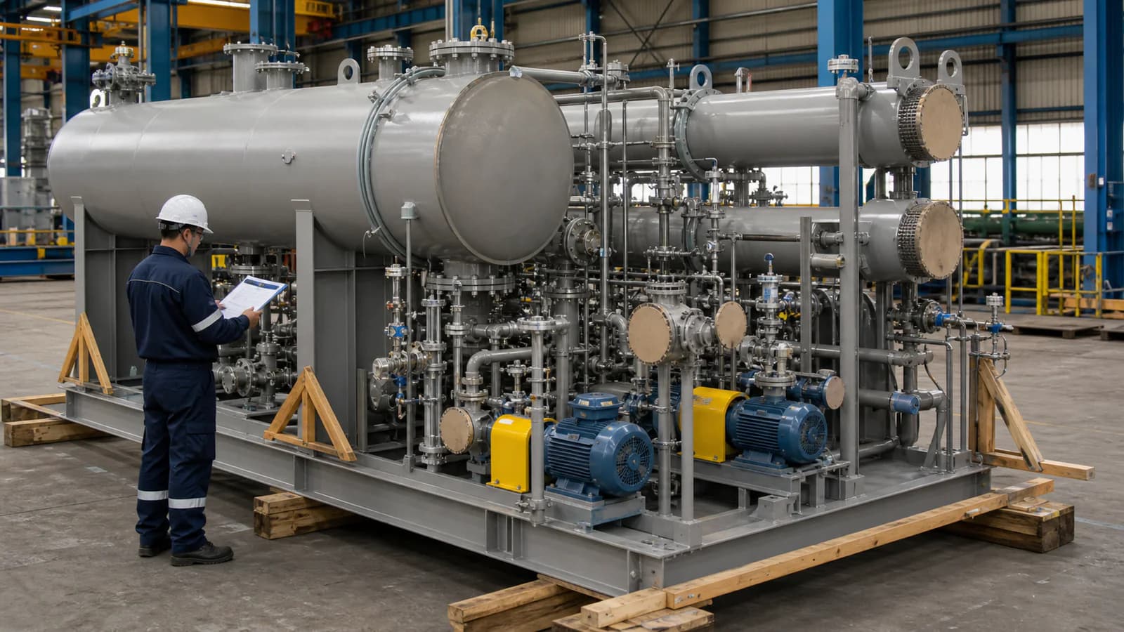
Factory testing can verify fabrication, equipment tags, piping, valves, pumps, instruments, controls, appropriate leak tests, clean-water operation, alarm simulation and documents. Factory water normally cannot reproduce FGD chemistry, so final metal, selenium, membrane, evaporator, condensate and solids performance requires representative feed and an agreed site or dedicated test.
Shipment inspection should verify preservation, lined surfaces, capped connections, membrane-storage requirements, rotating-equipment locks, loose parts, spares, lifting and packing. Large skids and evaporator bodies also require a transport and site-lifting plan.
Installation and Commissioning Preparation
Before delivery, confirm foundations, bunds, drains, lifting, ventilation, chemicals, sludge, brine and condensate tanks, utilities, controls and emergency storage. Commissioning should separate mechanical completion, flushing, calibration, chemical preparation, wastewater introduction, precipitation optimization, membrane or thermal startup, training and performance testing, with a route for off-spec water during stabilization.
Common Procurement Mistakes
- Treating FGD wastewater as a standard metal-precipitation package.
- Designing from TDS and pH without individual ions and trace contaminants.
- Maximizing RO recovery without a scaling and concentrate assessment.
- Specifying an evaporator without characterizing boiling, foaming and corrosion.
- Calling membrane permeate or condensate reusable without defining its destination.
- Assuming ZLD eliminates waste rather than producing solids and cleaning residuals.
- Omitting fuel, load and absorber-operation variation.
- Comparing capital price without energy, reagents, sludge and maintenance.
- Using one material grade across low-temperature water and hot concentrated brine.
- Requiring unconditional performance guarantees outside a defined influent envelope.
Frequently Asked Questions
What is the main treatment challenge in FGD wastewater?
There is no single challenge. High salts, scaling species, suspended solids, chloride corrosion, trace metals, selenium species and operating variation interact. The priority depends on the plant chemistry and final target.
Can chemical precipitation achieve ZLD?
No. It removes precipitable contaminants and suspended solids but leaves a liquid stream containing dissolved salts. ZLD requires additional water recovery and a final residual-management stage.
Can RO treat FGD wastewater?
RO may be part of a treatment train after suitable pretreatment. Feasibility depends on scaling, suspended solids, oxidation, pressure, recovery and concentrate management. Untreated FGD purge is not automatically suitable membrane feed.
When is evaporation required?
Evaporation may be considered when a ZLD target applies, membrane concentrate needs further volume reduction, or discharge is not viable. Its suitability depends on feed chemistry, energy, materials, condensate and solids handling.
Is MVR always more efficient than multi-effect evaporation?
No universal answer applies. MVR uses electrical compression of vapor; multi-effect systems commonly use steam across effects. Feed chemistry, boiling-point elevation, turndown, energy prices, heat integration, maintenance and scale determine the better configuration.
What information is most important for a supplier?
Provide representative ion and contaminant analyses with ranges, flow profile, FGD operating context, treatment objective, water balance, utilities, available footprint, material constraints and residual-disposal routes.
Conclusion
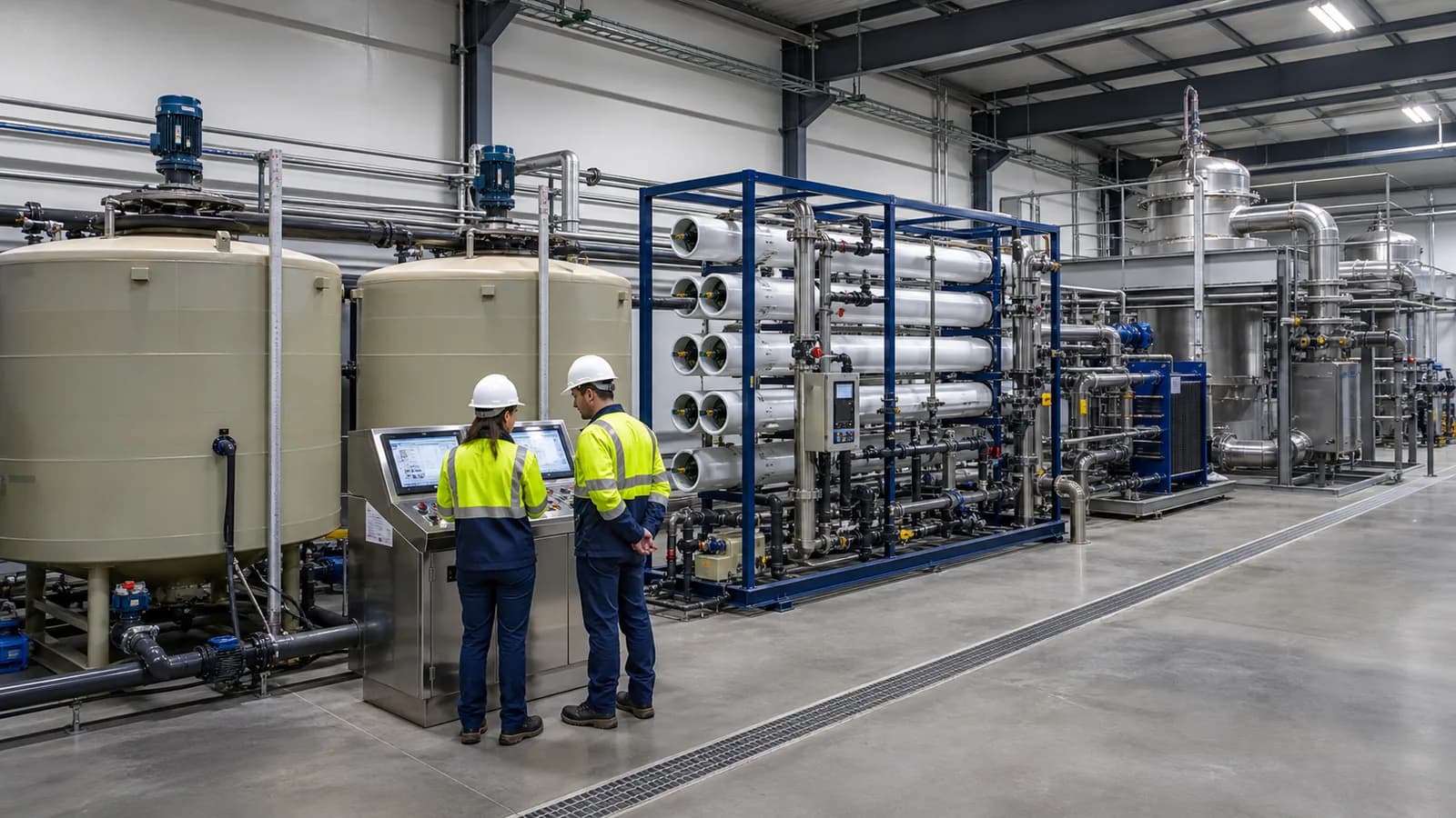
FGD wastewater treatment is a sequence of decisions about chemistry, water recovery and residuals. Conventional treatment can remove solids and precipitable metals. Biological or specialty polishing can target a defined dissolved-contaminant gap. Membranes can recover water and reduce brine flow. Thermal stages can support ZLD, but require the highest attention to energy, scaling, corrosion, condensate and solids.
Begin with a representative influent envelope and a whole-plant water and contaminant balance. Define the legal or reuse target, assign every process stage a clear role, test the uncertain steps and compare lifecycle boundaries. This produces a defensible procurement specification and reduces the risk of buying an isolated unit that cannot complete the plant’s wastewater strategy.
Send Your FGD Wastewater Requirements
Send Baihuipu the FGD process description, wastewater analyses and ranges, average and peak flow, plant water balance, discharge or ZLD objective, utilities, site conditions and residual-management plan. The team can review how conventional pretreatment, membrane concentration, evaporation or a combined route may fit the project, subject to confirmed chemistry and agreed performance conditions.
Continue with the wastewater evaporator selection guide and the discharge, reuse or ZLD decision framework.
CTA: Request an FGD Process Review